Youtube video about the above issue .
Deep dives into striNg data types – part 2
For this particular post, I’ll be exploring the following string manipulations methods. The code describes the various purpose of each string methods.
capitalize()
title()
upper()
swapcase()

Output upon running the scripts are shown below:

############### END ##########################
Deep Dives into String data Types – part 1
For this particular post, I will be exploring String data types. At a high level, will go into how string is entered and created in python. I am using VSCode as my IDE. I’ll be commenting what each particular code will do to make it for easier reference.
All my code executions is run within a virtual environment and the terminal will provide the details of the output upon running the python program as shown below.
Learning Points:
a. Commenting in python
b. Using the print function
c. VSCode as IDE

#######################END#######################################
Python Cheatsheets – Data types
Below is the various type of python data types.
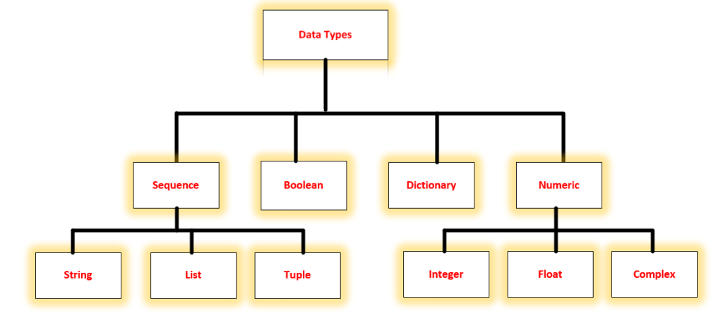
Brief descriptions for each data types:
Sequence: Ordered collections of similar or completely different data types. Three type of sequence:
a. String – any sequence of characters enclosed within a single quotes, double quotes or triple quotes.
b. List – any objects groupings stored in a variable which has the below characteristics:
– starts and end with a bracket, ordered, indexed, mutable, dynamic and can have
any types of object.
c. Tuple – It essentially the same as list except that its ummutable and starts and ends
with a parenthesis.
Boolean: provides a value of either True or False
Dictionary: represented in a format of a key-value pairs. Its an unordered collections of the same of completely different data types.
Numeric: this type has a numeric values which is categories into three sub-types: integer, float and complex number.
SSH Access using Netmiko – Extracting show version
After several months of being engaged on work related projects, I had again the opportunity to start updating my blog. For this particular post, i will be going through details on how did I setup my lab to access a device using Netmiko to extract any desired output.
Laboratory setup:
Below is my simple lab setup in EVE-NG. I am connecting to the switch through an Ubuntu server which is designated as a Cloud Network from the diagram below. The server is on the same network segment as my EVE-NG.

I will be using VSCode as my IDE. I will post another technical blog on how did I setup a connectivity from VSCode towards my Ubuntu dev machine.
High Level Steps:
- Configure the switch to provide SSH access from the dev machine.
- Validate the connectivity from the dev machine to the device.
- Run the Netmiko script to connect to the device
Below is the minimal required configurations to established the ssh access to the switch.
config t
hostname ccie-marathon-core-sw
int gi0/0
no switchport
ip address dhcp
no shut
ip domain-name cciemarathon.com
crypto key generate rsa general-keys modulus 2048
ip ssh version 2
username admin privilege 15 secret cciemarathon2022!
line vty 0 4
login local
transport input ssh
As confirmed below is configurations applied and the IP address assigned to the switch. The IP address allocated to Gi0/0 will be used to managed the device.
Switch#config t
Enter configuration commands, one per line. End with CNTL/Z.
Switch(config)#hostname ccie-marathon-core-sw
ccie-marathon-core-s(config)#int gi0/0
ccie-marathon-core-s(config-if)#no switchport
ccie-marathon-core-s(config-if)#ip dhcp address ^
ccie-marathon-core-s(config-if)#no shut
*May 9 20:42:14.640: %LINK-3-UPDOWN: Interface GigabitEthernet0/0, changed state to up
*May 9 20:42:15.643: %LINEPROTO-5-UPDOWN: Line protocol on Interface GigabitEthernet0/0, changed state to up
ccie-marathon-core-s(config-if)#
ccie-marathon-core-s(config-if)#ip domain-name cciemarathon.com
ccie-marathon-core-s(config)#
ccie-marathon-core-s(config)#$generate rsa general-keys modulus 2048
The name for the keys will be: ccie-marathon-core-sw.cciemarathon.com
% The key modulus size is 2048 bits
% Generating 2048 bit RSA keys, keys will be non-exportable…
[OK] (elapsed time was 0 seconds)
ccie-marathon-core-s(config)#ip ssh version 2
ccie-marathon-core-s(config)#
*May 9 20:41:41.652: %SSH-5-ENABLED: SSH 1.99 has been enabled
ccie-marathon-core-s(config)#
ccie-marathon-core-s(config)#line vty 0 4
ccie-marathon-core-s(config-line)#login local
ccie-marathon-core-s(config-line)#transport input ssh
ccie-marathon-core-s(config-line)#
ccie-marathon-core-s(config-line)#^Z
ccie-marathon-core-sw#
ccie-marathon-core-sw#
*May 9 20:42:39.575: %DHCP-6-ADDRESS_ASSIGN: Interface GigabitEthernet0/0 assigned DHCP address 192.168.0.146, mask 255.255.255.0, hostname ccie-marathon-core-sw
transport input ssh
*May 9 20:43:00.533: %SYS-5-CONFIG_I: Configured from console by consoleshow ip int br
ccie-marathon-core-sw#show ip int brief
Interface IP-Address OK? Method Status Protocol
GigabitEthernet0/0 192.168.0.146 YES DHCP up up
GigabitEthernet0/1 unassigned YES unset up up
GigabitEthernet0/2 unassigned YES unset up up
GigabitEthernet0/3 unassigned YES unset up up
GigabitEthernet1/0 unassigned YES unset up up
GigabitEthernet1/1 unassigned YES unset up up
GigabitEthernet1/2 unassigned YES unset up up
GigabitEthernet1/3 unassigned YES unset up up
Validating SSH access to the switch from the Dev Machine shows that SSH access is working from the Ubuntu host.

Netmiko Script to access the device is shown below,
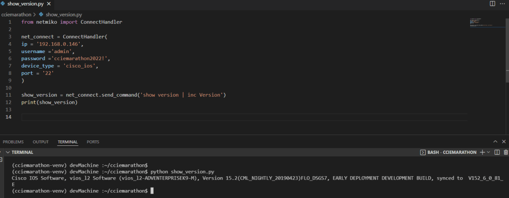
#############END######################
What if EVE-NG GUI is not accessible?
I’m setting up today a Palo Alto devices when suddenly after uploading the Panorama image and adding the Panorama and a pair of Palo Alto FW’s on my CCIE Marathon lab setup, EVE-NG Stop working…
Eve-NG Cookbook mentioned that it can be related to a disk allocations which is absolutely right…Well, I think, it would be worth re-creating everything again by starting to setup a new EVE-NG VM’s with a much higher disk space instead of adding new disk space on my existing EVE-NG VM.
Installing PYATS, Setting up Testbeds and Using Parse Module
CCIE Marathon discussed the below topics on this video:
- pyats installation and handling the errors encountered during installations
- created testbed based on his lab setup
- export credentials of lab device to the devops machine
- test the pyats parse module
- used IDE VSCode to manage or run the scripts
Errors Encountered during the pyats installations:
ERROR: Failed building wheel for pyftpdlib
Running setup.py clean for pyftpdlib
Building wheel for tftpy (setup.py) … error
ERROR: Command errored out with exit status 1:
command: /home/admin01/workspace/pyats/pyats_venv/bin/python3 -u -c ‘import sys, setuptools, tokenize; sys.argv[0] = ‘”‘”‘/tmp/pip-install-dpcslmz8/tftpy/setup.py'”‘”‘; file='”‘”‘/tmp/pip-install-dpcslmz8/tftpy/setup.py'”‘”‘;f=getattr(tokenize, ‘”‘”‘open'”‘”‘, open)(file);code=f.read().replace(‘”‘”‘\r\n'”‘”‘, ‘”‘”‘\n'”‘”‘);f.close();exec(compile(code, file, ‘”‘”‘exec'”‘”‘))’ bdist_wheel -d /tmp/pip-wheel-jnuzsri1
cwd: /tmp/pip-install-dpcslmz8/tftpy/
Complete output (6 lines):
usage: setup.py [global_opts] cmd1 [cmd1_opts] [cmd2 [cmd2_opts] …]
or: setup.py –help [cmd1 cmd2 …]
or: setup.py –help-commands
or: setup.py cmd –help
error: invalid command ‘bdist_wheel’
ERROR: Failed building wheel for tftpy
Running setup.py clean for tftpy
Failed to build yamllint async-lru backports.ssl pyftpdlib tftpy
Installing collected packages: six, junit-xml, pyats.results, pyats.datastructures, python-engineio, python-socketio, async-lru, idna, multidict, yarl, frozenlist, aiosignal, charset-normalizer, attrs, async-timeout, aiohttp, MarkupSafe, jinja2, pyyaml, aiohttp-swagger, chardet, aiofiles, pyats.log, psutil, pyats.aereport, pycparser, cffi, cryptography, pyats.async, dill, unicon.plugins, unicon, pyats.connections, pathspec, yamllint, pyats.topology, distro, pyats.utils, pyats.aetest, urllib3, certifi, requests, pyats.kleenex, smmap, gitdb, gitpython, pyats.reporter, pyats.easypy, pyats.tcl, robotframework, genie.libs.robot, click, python-dateutil, arrow, jinja2-time, poyo, text-unidecode, python-slugify, binaryornot, cookiecutter, netaddr, jsonpickle, wcwidth, PrettyTable, xmltodict, genie.libs.parser, pyftpdlib, tftpy, genie.libs.filetransferutils, wheel, genie.libs.health, genie.libs.ops, genie.libs.conf, genie.libs.clean, ruamel.yaml.clib, ruamel.yaml, genie.libs.sdk, tqdm, genie, genie.telemetry, backports.ssl, websocket-client, pyopenssl, ixnetwork, ixnetwork-restpy, genie.trafficgen, pyats.robot, xlrd, xlsxwriter, xlwt, requests-toolbelt, pyats.contrib, pyats
Running setup.py install for async-lru … done
Running setup.py install for yamllint … done
Running setup.py install for pyftpdlib … done
Running setup.py install for tftpy … done
Running setup.py install for backports.ssl … done
Python Cheatsheets
Install Python 3 Virtual Environments in Ubuntu
sudo apt update
sudo apt upgrade
apt install python3-pip
apt-get install python3-venv
To create Virtual Environment
python3 -m venv venv
To Activate Virtual Environments
source venv/bin/activate
To Exit from Virtual environments
deactivate
Exploring OSPF Network Types
On this post, I wlll be exploring concepts of OSPF network Types and look into some details of some attributes required to established OSPF neighbors.
Key Task:
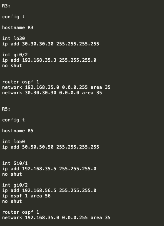
I will be using the below topology to explore on this lab but for this particular concepts, I will just be using R3, R5 and R6 for this lab both on OSPF process 1. R3 and R5 will be in OSPF area 35 while R5 and R6 will be in OSPF area 56. To explore the ways to enable OSPF, both R3 and R5 will be using the network statement to enable OSPF while for R5 and R6, OSPF will be enabled under interface mode. ALl the loopbacks needs to be advertise on both R3 and R6.
Topology:

Configurations:

Verifications:
- Verify that the interfaces are assigned on correct ospf areas as per the requirements using “show ip ospf interface brief”


As observed above, the coorect areas were assigned , example for R5 which is the middle router has both areas facing R3 as area 35 and facing R6 as area 56…
2. Check that the OSPF neighbors were formed:

as observed, OSPF neighbors were formed and R5 is showinga s the DR or designated router..
With the DR/BDR showing on the State, this simply suggest that the OSPF network types were a BROADCAST..
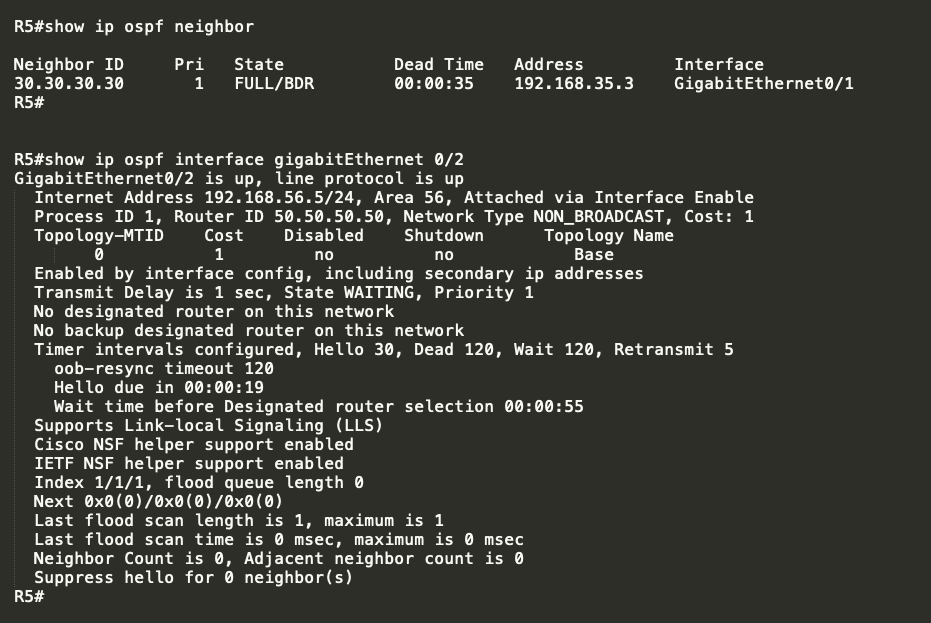
3. To verify the OSPF network type, the command “show ip ospf interface ” can be use.

From the above results, there are several informations provided on the output such as the following:
** The AREA is 56
** Attached via Interface Enable –> this means that the OSPF is enabled under the interface mode using the command “ip ospf 1 area 56”
** The Network Type is BROADCAST
** The OSPF cost is 1
** The Designated Router ID is 50.50.50.50 which is R5.
** The backup designated router is 60.60.60.60 which is R6
** The hello Interval is 10 sec with 40 as the Dead Interval ( which by default will automatically set as 4 times the Hello interval)
4. Lets check the topology table….

>> The Router LSA on area 35 shows two details which is the loopback of R3 and R5 ( this is the router ID of both routers)
>> The Network Link LSA under area 35 also shows the IP address of the R5 which is used to formed the OSPF neighbor. This is local on R5.
>> Similarly, Router LSA on area 56 shows the router ID of R5 and R6
>> The Network Link LSA also shows the IP address of the link on R5 that is used to formed the OSPF neighbors. This is local on R5.
5. Lets check thew routing table by this time…


>> as expected R5 wil learned about R3 and R6 loopbacks as this was advertise from both routers…
>> But R3 and R6 will not learned each other’s loopback as there was no backbone area that was set up..
>> NOTE: OSPF MUST NEED a backbone area in order to provide communications between two different areas.
Let me just advertise R5 loopback on area 35 to elaborate what I mean here…

- Let me explore on checking the two attributes which is required to match (supported) in order to established OSPF neighbors:
*** Network Types
*** Hello Interval
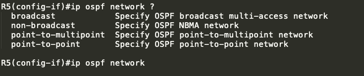
By default, OSPF interface are using BROADCAST….
Let me try changing this to non-broadcast…

As observed the OSPF neighbor towards R6 went …
Lets try to change the network type to point-to-multipoint:
Revert first to Broadcast:

and change to point-to-multipoint

again OSPF does not like it..
Finally, lets try to used “POINT-TO-POINT”

It shows on R5 that a potential network type mistmatch but still it formed the OSPF neighbors…

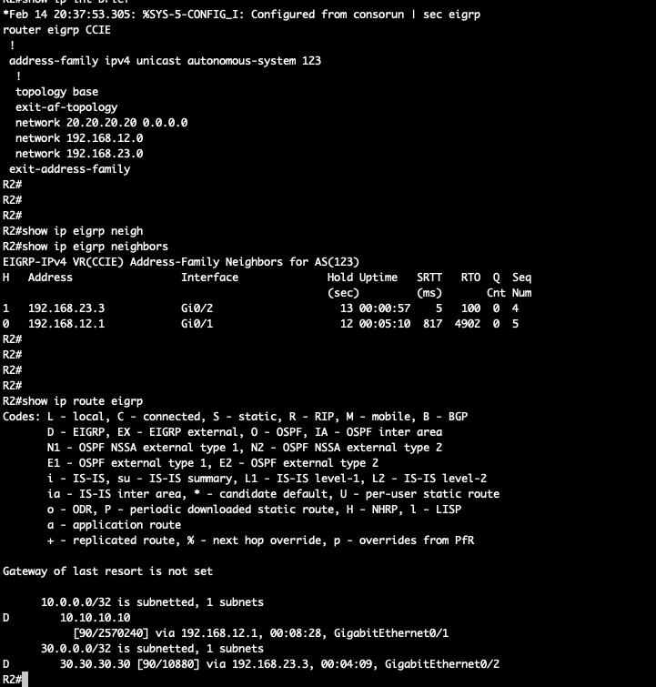
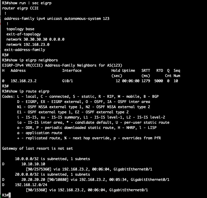
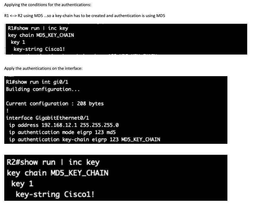
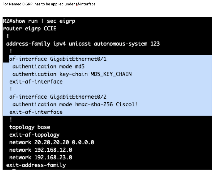
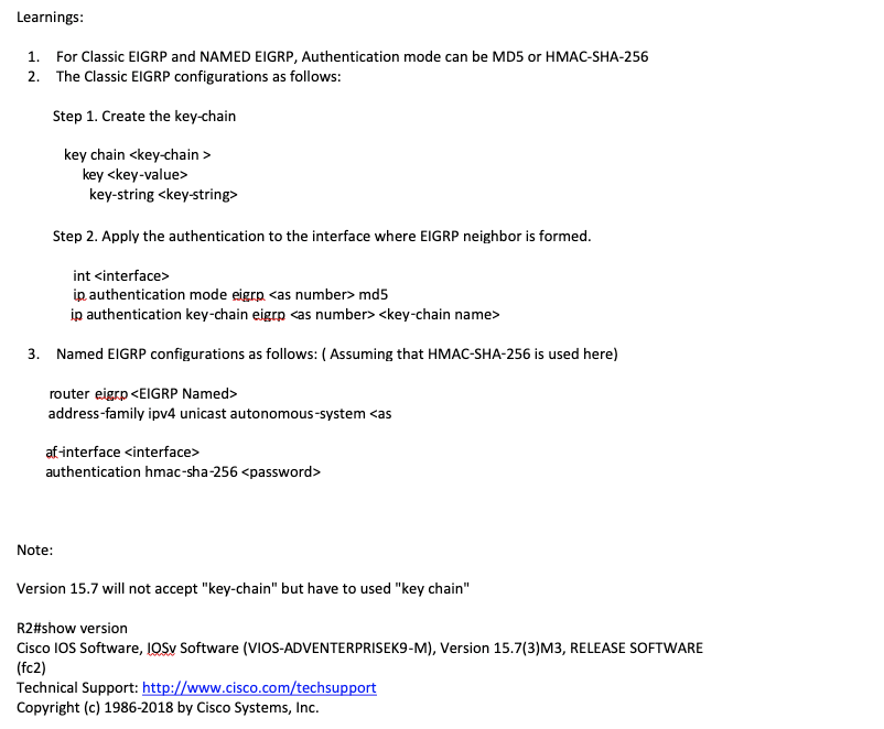
Exploring EIGRP Authentications for both Classic and Named EIGRP
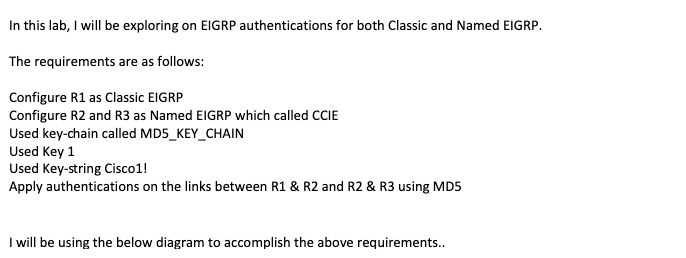
Configurations:

EIGRP Leak-Map
Had to do a lot labs for my CCIE LAB preparations…One of the interesting EIGRP Concept which I’m gonna post is with EIGRP leak-maps…
So basically, when EIGRP is enabled and we started advertising the routes, each network advertise will be received by the neighboring EIGRP router…
So what if we want to select the routes which we want to advertise when summarization is enabled… Summarization is useful if we just want a single network to be advertise…but what if a requirements is not to advertise a certain network address that belongs to the summarized network…
This can be done via a leak-map…had to explore a bit on classic EIGRP and Named EIGRP in order to elaborate more on leak-map…
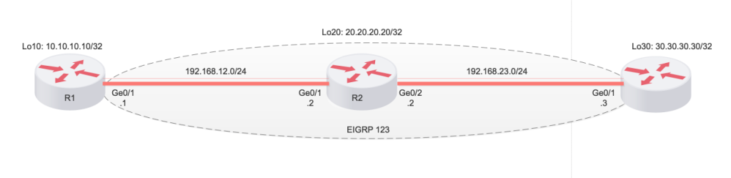
I’m gonna used the below simple diagram to explore on this concept..
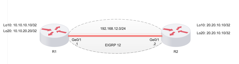
Below are the task that needs to be completed…
- Configure R1 as Classic EIGRP
- Configure R2 as Named EIGRP
- Configure Summary routes in R1. Allow Only Loopback 10 in R1 to be learned by R2.
- Configure Summary routes in R2. Allow only Loopback 20 in R2 to be learned by R1.
Configurations:

R1:

router eigrp 12
 network 10.10.10.10 0.0.0.0
 network 10.10.20.20 0.0.0.0
 network 192.168.12.0


Named EIGRP Configurations:

 R2:

 router eigrp NAMED_R1-R2
 !
 address-family ipv4 unicast autonomous-system 12
  !
  topology base
  exit-af-topology
  network 20.20.10.10 0.0.0.0
  network 20.20.20.20 0.0.0.0
  network 192.168.12.0
 exit-address-family


EIGRP neighbor verifications:

R1#show ip eigrp neighbors
EIGRP-IPv4 Neighbors for AS(12)
H   Address                 Interface              Hold Uptime   SRTT   RTO  Q  Seq
                                                   (sec)         (ms)       Cnt Num
0   192.168.12.2            Gi0/1                    11 00:00:47    2   100  0  5


R2#show ip eigrp neighbors
EIGRP-IPv4 VR(NAMED_R1-R2) Address-Family Neighbors for AS(12)
H   Address                 Interface              Hold Uptime   SRTT   RTO  Q  Seq
                                                   (sec)         (ms)       Cnt Num
0   192.168.12.1            Gi0/1                    12 00:00:28 1021  5000  0  4
R2#


EIGRp routing table without Summarization:


 R1#show ip route eigrp
Codes: L - local, C - connected, S - static, R - RIP, M - mobile, B - BGP
       D - EIGRP, EX - EIGRP external, O - OSPF, IA - OSPF inter area
       N1 - OSPF NSSA external type 1, N2 - OSPF NSSA external type 2
       E1 - OSPF external type 1, E2 - OSPF external type 2
       i - IS-IS, su - IS-IS summary, L1 - IS-IS level-1, L2 - IS-IS level-2
       ia - IS-IS inter area, * - candidate default, U - per-user static route
       o - ODR, P - periodic downloaded static route, H - NHRP, l - LISP
       a - application route
       + - replicated route, % - next hop override, p - overrides from PfR

Gateway of last resort is not set

      20.0.0.0/32 is subnetted, 2 subnets
D        20.20.10.10 [90/2848] via 192.168.12.2, 00:00:40, GigabitEthernet0/1
D        20.20.20.20 [90/2848] via 192.168.12.2, 00:00:33, GigabitEthernet0/1


R2#show ip route eigrp
Codes: L - local, C - connected, S - static, R - RIP, M - mobile, B - BGP
       D - EIGRP, EX - EIGRP external, O - OSPF, IA - OSPF inter area
       N1 - OSPF NSSA external type 1, N2 - OSPF NSSA external type 2
       E1 - OSPF external type 1, E2 - OSPF external type 2
       i - IS-IS, su - IS-IS summary, L1 - IS-IS level-1, L2 - IS-IS level-2
       ia - IS-IS inter area, * - candidate default, U - per-user static route
       o - ODR, P - periodic downloaded static route, H - NHRP, l - LISP
       a - application route
       + - replicated route, % - next hop override, p - overrides from PfR

Gateway of last resort is not set

      10.0.0.0/32 is subnetted, 2 subnets
D        10.10.10.10
           [90/2570240] via 192.168.12.1, 00:00:56, GigabitEthernet0/1
D        10.10.20.20
           [90/2570240] via 192.168.12.1, 00:00:56, GigabitEthernet0/1
R2#


First Condition is for R1 to leak only L10 to R2 and summary routes from R1 should be seen on R2:


Configs to apply:

int gigabitEthernet 0/1
ip summary-address eigrp 12 10.10.0.0/16 leak-map R1R2_Leak_Map

ip prefix-list R1_to_R2-Leak_Routes permit 10.10.10.10/32

route-map R1R2_Leak_Map
match ip address prefix-list R1_to_R2-Leak_Routes


R1#config t
Enter configuration commands, one per line.  End with CNTL/Z.
R1(config)#int gigabitEthernet 0/1
R1(config-if)#ip summary-address eigrp 12 10.10.0.0/16 leak-map R1R2_Leak_Map

*Feb 12 11:55:17.688: %DUAL-5-NBRCHANGE: EIGRP-IPv4 12: Neighbor 192.168.12.2 (GigabitEthernet0/1) is resync: summary configured
R1(config-if)#


Used Prefix-list to filter the Loopback 20...


R1(config)#ip prefix-list R1_to_R2-Leak_Routes permit 10.10.10.10/32


Create the route-map ...


R1(config)#route-map R1R2_Leak_Map
R1(config-route-map)#match ip address prefix-list R1_to_R2-Leak_Routes
R1(config-route-map)#^Z
R1#
R1#
R1#
R1#
*Feb 12 11:57:05.672: %SYS-5-CONFIG_I: Configured from console by console
R1#
R1#
*Feb 12 11:57:14.552: %DUAL-5-NBRCHANGE: EIGRP-IPv4 12: Neighbor 192.168.12.2 (GigabitEthernet0/1) is resync: intf route configuration changed

Now checking R2 EIGRP Topology table:

R2#show ip eigrp topology
EIGRP-IPv4 VR(NAMED_R1-R2) Topology Table for AS(12)/ID(20.20.20.20)
Codes: P - Passive, A - Active, U - Update, Q - Query, R - Reply,
       r - reply Status, s - sia Status

P 10.10.10.10/32, 1 successors, FD is 328990720
        via 192.168.12.1 (328990720/327761920), GigabitEthernet0/1
P 192.168.12.0/24, 1 successors, FD is 1310720
        via Connected, GigabitEthernet0/1
P 20.20.20.20/32, 1 successors, FD is 163840
        via Connected, Loopback20
P 20.20.10.10/32, 1 successors, FD is 163840
        via Connected, Loopback10
P 10.10.0.0/16, 1 successors, FD is 328990720
        via 192.168.12.1 (328990720/327761920), GigabitEthernet0/1

R2#


It has only the topology entry for the summary routes from R1 and Loopback 10..


R2#show ip route eigrp
Codes: L - local, C - connected, S - static, R - RIP, M - mobile, B - BGP
       D - EIGRP, EX - EIGRP external, O - OSPF, IA - OSPF inter area
       N1 - OSPF NSSA external type 1, N2 - OSPF NSSA external type 2
       E1 - OSPF external type 1, E2 - OSPF external type 2
       i - IS-IS, su - IS-IS summary, L1 - IS-IS level-1, L2 - IS-IS level-2
       ia - IS-IS inter area, * - candidate default, U - per-user static route
       o - ODR, P - periodic downloaded static route, H - NHRP, l - LISP
       a - application route
       + - replicated route, % - next hop override, p - overrides from PfR

Gateway of last resort is not set

      10.0.0.0/8 is variably subnetted, 2 subnets, 2 masks
D        10.10.0.0/16
           [90/2570240] via 192.168.12.1, 00:08:39, GigabitEthernet0/1
D        10.10.10.10/32
           [90/2570240] via 192.168.12.1, 00:06:57, GigabitEthernet0/1
R2#


Configure R2 to filter Loopback 10 and allow only Loopback 20 and enable summary routes...

Script:

router eigrp NAMED_R1-R2
 !
 address-family ipv4 unicast autonomous-system 12
  !
  af-interface GigabitEthernet0/1
   summary-address 20.20.0.0 255.255.0.0 leak-map R2_R1_Leak_Map
  exit-af-interface


ip prefix-list R2_R1_Leak_Routes permit 20.20.20.20/32

route-map R2_R1_Leak_Map
match ip address prefix-list R2_R1_Leak_Routes


Configurations applied on the device...

R2(config)#router eigrp NAMED_R1-R2
R2(config-router)# address-family ipv4 unicast autonomous-system 12
R2(config-router-af)#af-interface Gi0/1
R2(config-router-af-interface)#summary-address 20.20.0.0 255.255.0.0 leak-map R2_R1_Leak_Map
R2(config)#ip prefix-list R2_R1_Leak_Routes permit
R2(config)#ip prefix-list R2_R1_Leak_Routes permit 20.20.20.20/32
R2(config)#route-map R2_R1_Leak_Map
R2(config-route-map)#match ip address prefix-list R2_R1_Leak_Routes

R2#
*Feb 12 12:12:24.030: %SYS-5-CONFIG_I: Configured from console by console
*Feb 12 12:12:32.722: %DUAL-5-NBRCHANGE: EIGRP-IPv4 12: Neighbor 192.168.12.1 (GigabitEthernet0/1) is resync: intf route configuration changed
R2#

Now checking R1 EIGRP routes:

R1#show ip route eigrp
Codes: L - local, C - connected, S - static, R - RIP, M - mobile, B - BGP
       D - EIGRP, EX - EIGRP external, O - OSPF, IA - OSPF inter area
       N1 - OSPF NSSA external type 1, N2 - OSPF NSSA external type 2
       E1 - OSPF external type 1, E2 - OSPF external type 2
       i - IS-IS, su - IS-IS summary, L1 - IS-IS level-1, L2 - IS-IS level-2
       ia - IS-IS inter area, * - candidate default, U - per-user static route
       o - ODR, P - periodic downloaded static route, H - NHRP, l - LISP
       a - application route
       + - replicated route, % - next hop override, p - overrides from PfR

Gateway of last resort is not set

      10.0.0.0/8 is variably subnetted, 3 subnets, 2 masks
D        10.10.0.0/16 is a summary, 00:17:28, Null0
      20.0.0.0/8 is variably subnetted, 2 subnets, 2 masks
D        20.20.0.0/16 [90/2848] via 192.168.12.2, 00:01:52, GigabitEthernet0/1
D        20.20.20.20/32
           [90/2848] via 192.168.12.2, 00:00:36, GigabitEthernet0/1
R1#


As observed, we have the summary routes from R2 and Loopback 20...
BGP Aggregate Routes
On this post, I will be exploring BGP route summarizations. I will be using the below topology to expand further on this topic.
From the topology, below are some informations to consider:
- R1 and R2 is represented as CE1 and CE2 which is connected to PE1 and PE2, respectively via eBGP
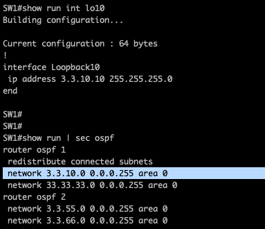
- R1 is connected to SW1 and is running OSPF, while R2 is connected to SW2 and is also running OSPF.
- The SW are advertising the following network address into OSPF:
4. Redistributed the connected prefixes with loopbacks 1,2,3 and 4.
5. Loopback 5 and 6 is learned from another OSPF process ( simulating another network downstream)

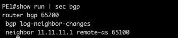
eBGP peering between CE1 and PE1:

iBGP peering between CE1 <–> CE2 and eBGP peering between CE2 and PE2

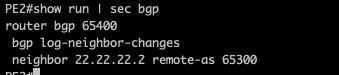


So from the output above, we can confirmed that both CE1 and CE2 are forming the eBGP towards the PE routers and iBGP for both CE’s.
So lets check the OSPF configurations on R1 <–> SW1:
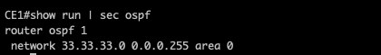


Lets check the OSPF neighbors:
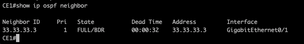

and the prefix learned by CE1 via OSPF:
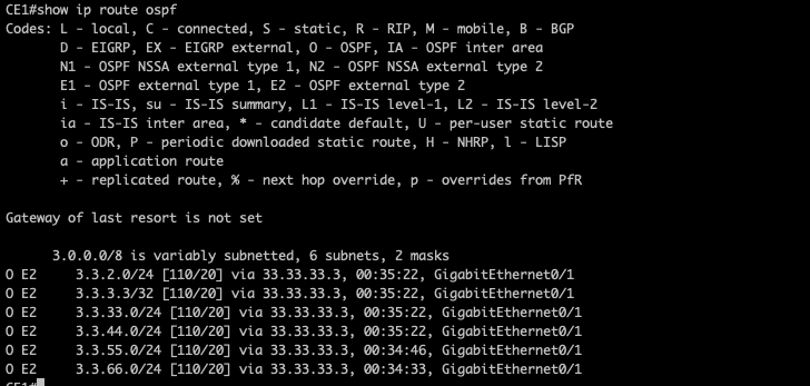
All the prefixes are learned as External OSPF routes by CE1.
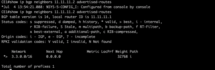
Now let me advertise the same prefixes into BGP in CE1.

As observed above CE is advertising the prefixes towards the PE1.
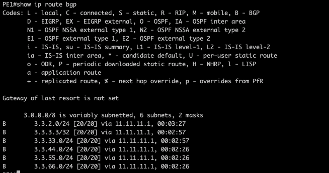
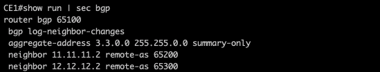
And PE1 is also receiving the same prefixes. Now let me add and aggregate summary for the prefixes on CE1:

And as expected, CE1 is sending a summary route on PE1:

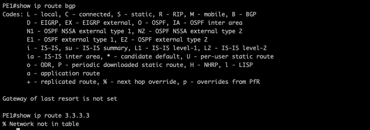
PE1 router is receiving the same summary routes from CE1 with Admin distance of 20(eBGP).
Adding another subnets on SW1 as follows :
Let me take all the individual prefixed added into BGP and just leaved the aggregate-address,
As observed, the prefixed is no longer available on CE1 routing table,

Note: In order to perform route aggregations in BGP, the prefixed must be advertise via network statement,
Now, let me add the same prefixes into BGP again.

As noticed the aggregate routes is added into BGP routing table and is again advertised into the PE router.

Would expect the same aggregate routes on CE2,

Static NAT issues with BGP
I been revisiting lately couple of notes/lab related to Network Address Translations and I think it’s worth to make some write ups on my observations when STATIC NAT is used with BGP.
So basically, Static NAT is a one-to-one mapping of any internal IP address in order to access any servers in the internet. In my experience, I have seen a deployment of static NAT on firewalls for inbound connections in particular servers that are connected on external DMZ’s, e.g. reverse proxy servers.

Configuration requirements:
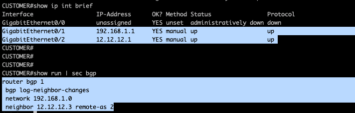
- Run eBGP between Customer router and ISP
- Advertise the internal IP address of Customer ( in production network, this is possible but private IP will definitely not routable and NAT is required. I am intentionally advertising 192.168.1.0/24 so I could analyze some logs on how IP packet traverse on the network)
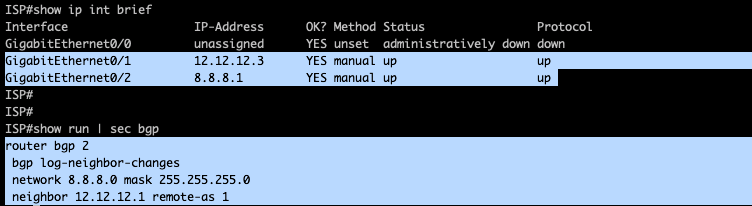
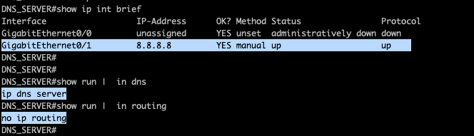
- Advertise 8.8.8.0/24 on BGP from ISP router so this will be reachable from HOST-A.
Configuration:
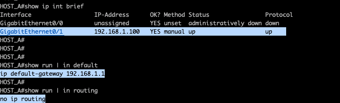
I’m using a router for my host so the above configurations is required. I’m disabling ip routing capabilities and pointing my default-gateway to gateway router.
ISP configs:
DNS Server configs.
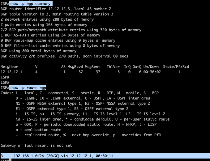
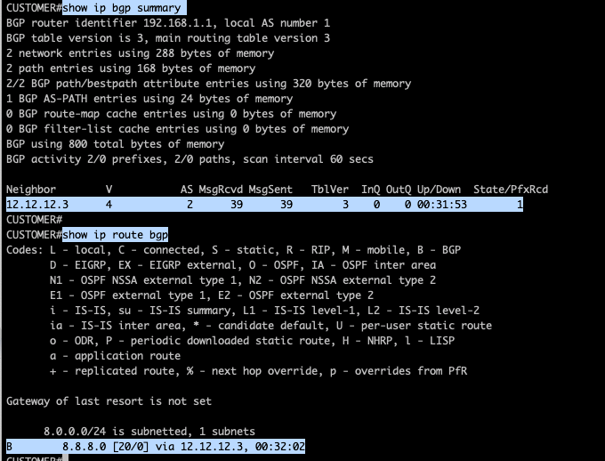
BGP neighbors were formed as seen below:
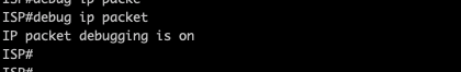
Just to check the traffic between Host-A towards the DNS server, I will be enabling debug on all the devices using ‘debug ip packet“command while running a ping from Host-A towards the DNS server IP 8.8.8.8.
example below which I have run for the ISP router…
Logs on Host-A:
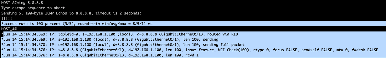
We could see traffic from 192.168.1.100 towards 8.8.8.8.
Logs on Customer router:
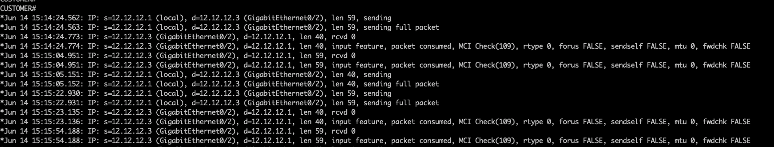
As the packet reaches Customer router with the destination 8.8.8.8, it tries to lookup its routing table and could find the destination address reachable via 12.12.12.3. The router have change the original ip packet with the egress interface IP address as the source of the ip packet and the ingress interface IP of ISP router as the destination ip address.
Logs on DNS server:

Logs is showing original ip packet with source ip address of 192.168.1.100 and destination 8.8.8.8. This is expected without network address translations.
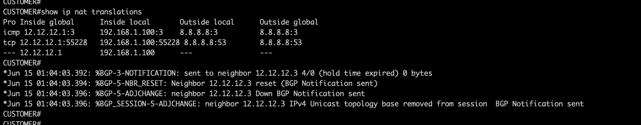
Now let me enable STATIC NAT on the Customer router.

To my surprise, I could see a few seconds BGP notification messages ( BGP notifications in BGP means a BAD message ) and the BGP sessions between Customer router and ISP router eventually transition into an ACTIVE state.

As I am aware that my BGP peering is only configured between the IP address of the direct link, I had a thought this could be an issue with NAT as every-time I’m removing the NAT applied on Customer router , BGP sessions were established.
As this is a STATIC NAT , one possible options I could think to solve this issue is to change the BGP peering address, e.g. using a loopback interface
But before going for that options, I will try to used the public facing interface for the translation.

BGP notifications did not immediately came in, as I still manage to run some testing but eventually the BGP sessions went into an ACTIVE state.
With this observations, I know that the inside global address should be routable IP to the internet, the only options is to change the BGP peering with the loopback address.
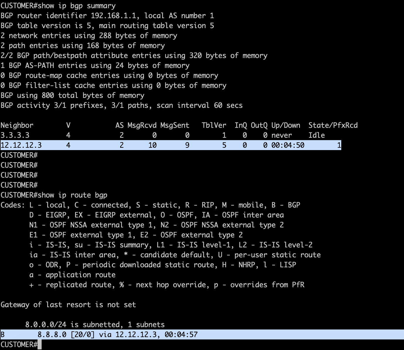
I have added a loopback address in the Customer router and added a static route for reachability and configured BGP using the loopback address:

Did the same for the ISP router,

and I could see BGP is up and prefix is advertise/received,
Considering the current NAT configurations on the Customer router, i did my testing to check the translations.

Did a ping and telnet from Host-A and observed translation on the Customer router, NAT table shows the Inside Global address which is the public address of customer router, Inside Local Address which is the private address of Host-A and also both the Outside Local & Outside Global address which is the DNS server. As observed, we could see the corresponding source port which is maintain through out the sessions.
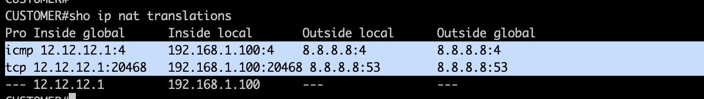
One interesting logs as captured from the DNS server shows that the source address is no longer 192.168.1.100 but changed to 12.12.12.1.

Take away from this lab:
- STATIC NAT Configurations
ip nat source static <inside global address> < outside global address>
2. Enable NAT on the interface:
interface GigabitEthernet0/1
ip nat inside
interface GigabitEthernet0/2
ip nat outside
4. To verify NAT translation:
show ip nat translation
5. BGP does not like that STATIC NAT Inside Global address as a peering IP. Options is to source the BGP TCP connections using a loopback address.
6. On troubleshooting part, use “debug ip packet”. This gives some informations of the source/destination IP during a testing.
********************END OF LAB ****************************************
PPP CHAP One-Way Authentication
In my previous post about PPP PAP Authentication, I have explored on the how to configure PAP for both One-Way authentications and Two-Way Authentications.
On this post, I will be exploring another method of PPP authentications which is called CHAP or Challenge Handshake Authentication Protocol. How CHAP works is that it uses a three way handshake to exchange and validate the authenticity of the participating devices before PPP sessions are activated.
The client router is manually configured with the remote username and password . For both PPP PAP and PPP CHAP One-way authentications, the client router has no “ppp authentication” configurations under the interface mode. This is the distinct difference between a Two-way authentications in terms of the configurations.
Let’s jump into the device configurations with the following LAB topology.

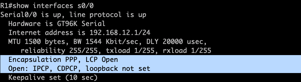
R1: Highlighted the configurations which I have added on R1
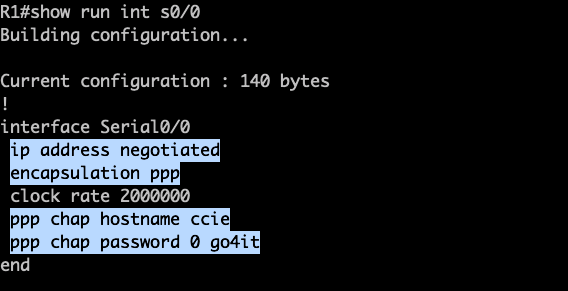

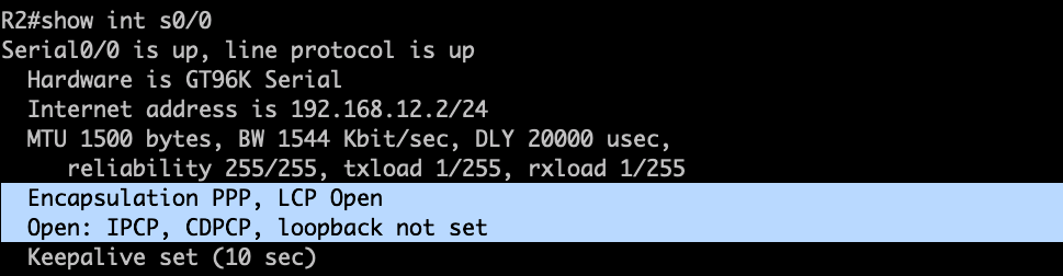
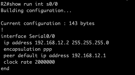
R2: Highlighted the configurations which I have added on R2.
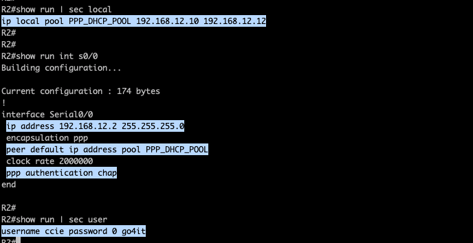
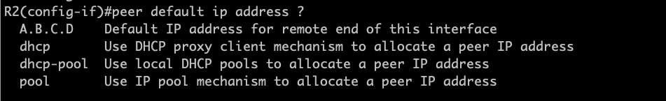
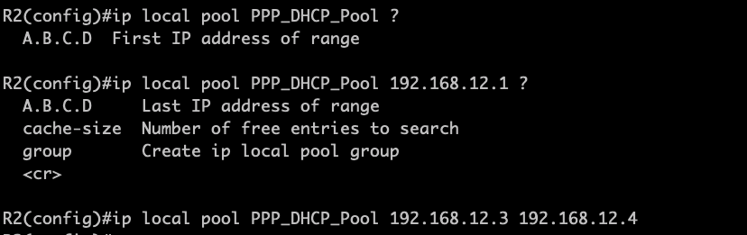
Again on R2, I have the the IP Pool that will be assigned on R1. PPP authentication is enabled and I have the username and password that will be used by R1 for the CHAP handshake initiated by R2.
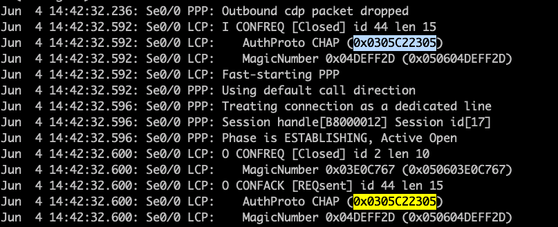
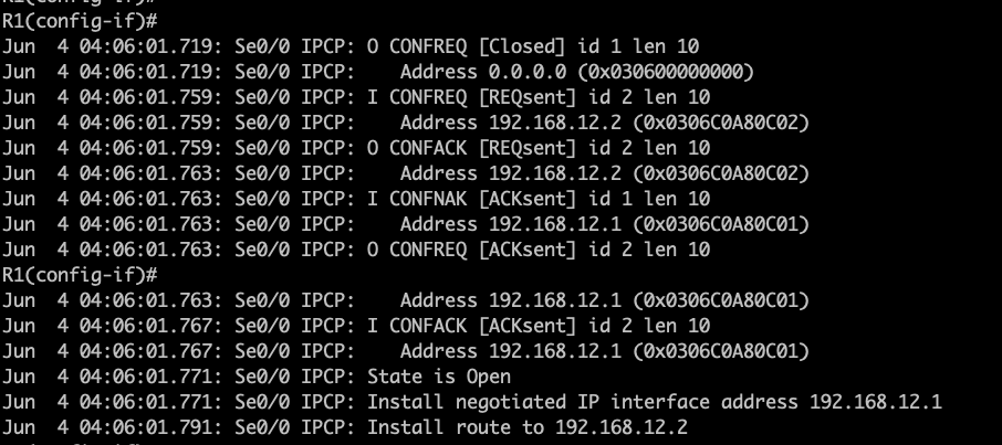
Let me enable the interface in R1 while running a debug to analyzed the PPP negotiations.
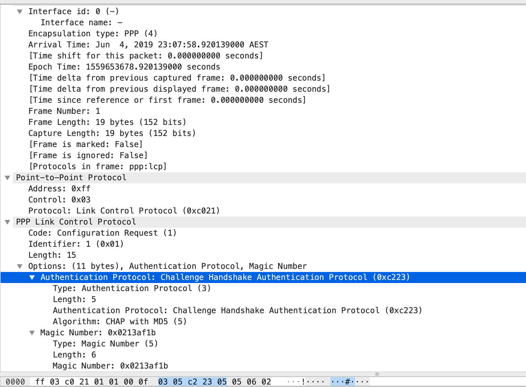
- Both routers agreed to used CHAP.
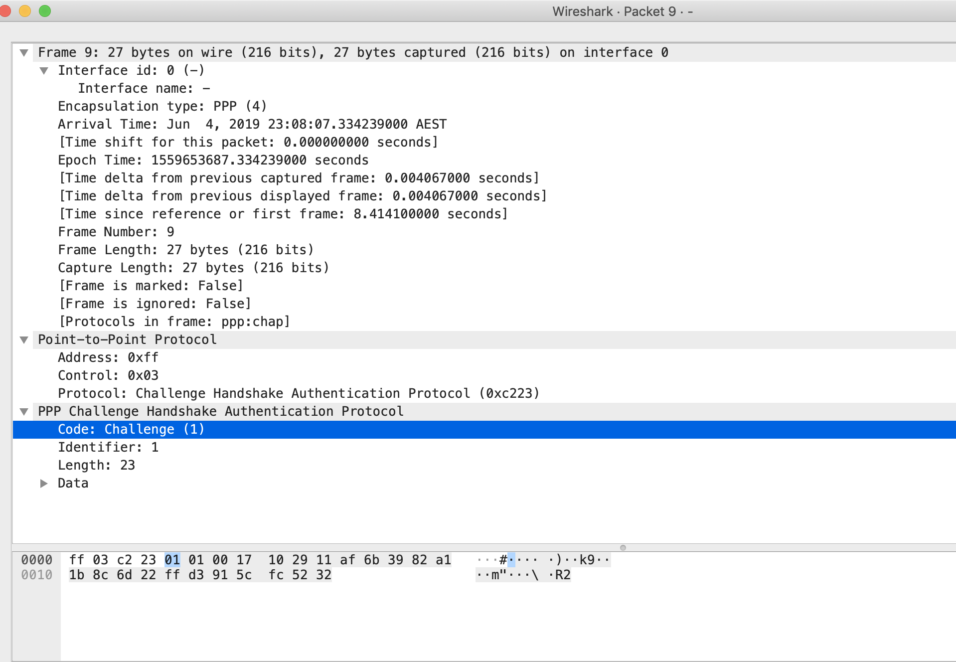
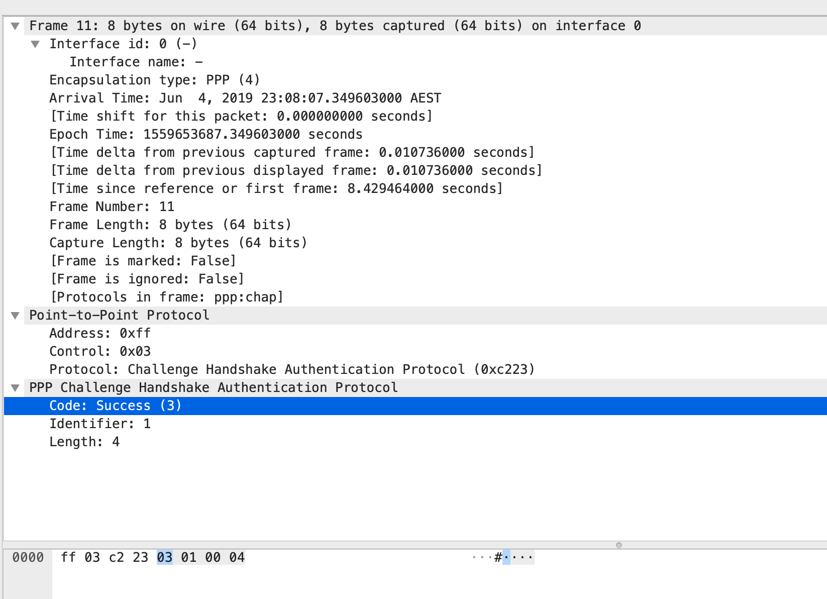
2. R1 received a CHAP challenge from R2. The way how this works is that R2 is sending a CHAP challenge with R1. R2 is generating a random MD5 hashing value which includes the local router authentications and this MD5 value is sent out to R1. In response, R1 have created with own version of hashing value which includes details of the existing authentication configured and this is sent out towards R2. R2 will then check the CHAP response and when it decode that R1 is using the same authentication, it will send out a SUCCESS Message to R1, thus both of them are now friends. 🙂


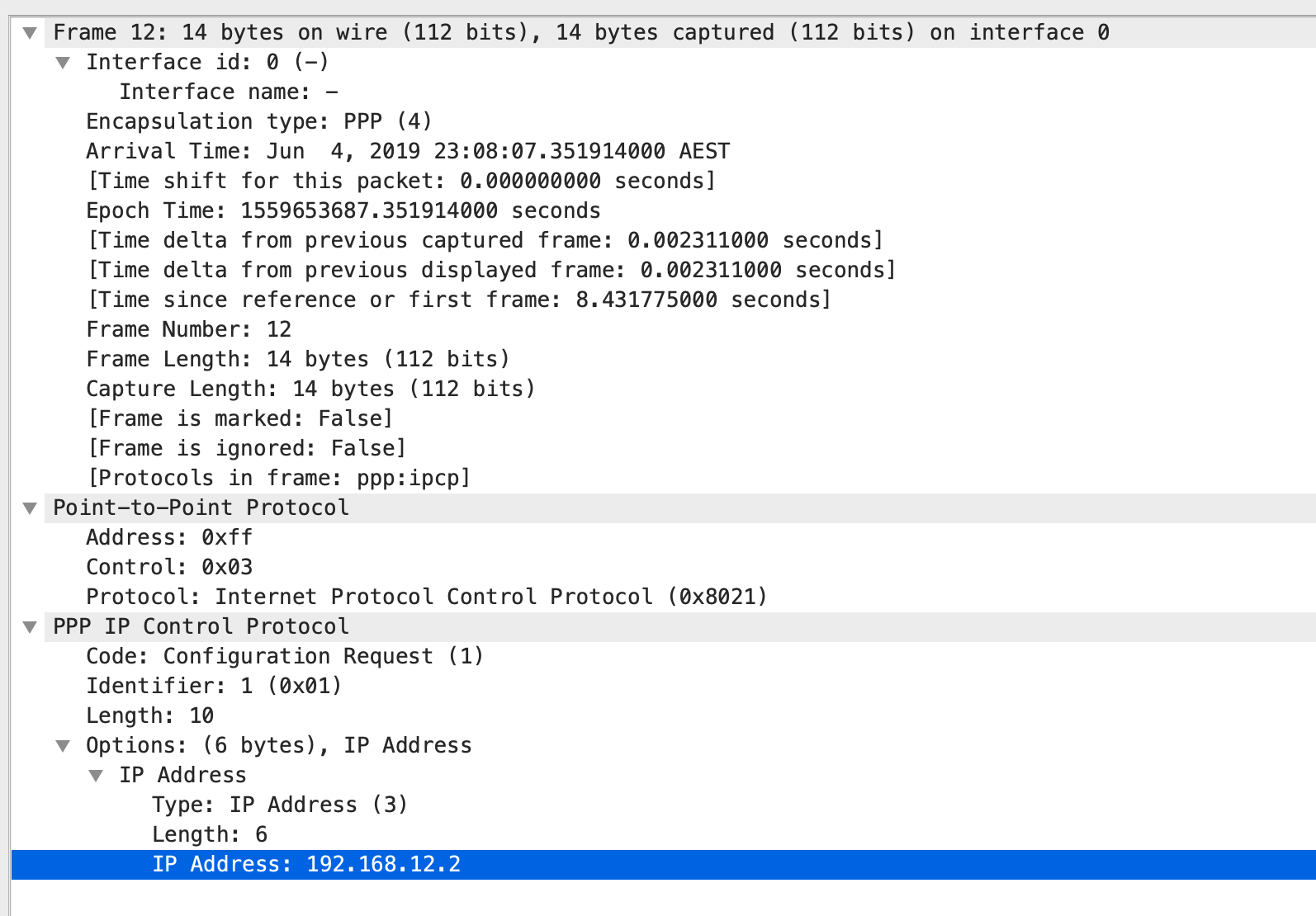
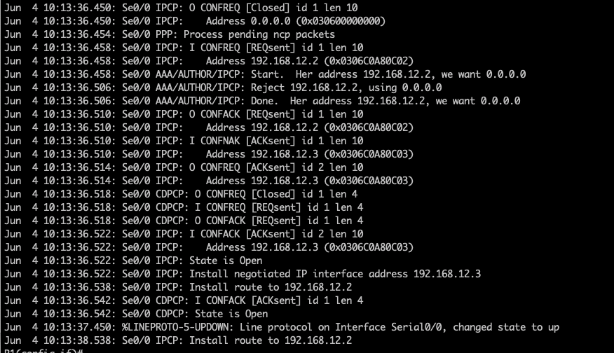
3. PPP Internet Protocol Control Protocol (IPCP) and PPP Cisco Discovery Protocol Control Protocol (CDPCP) will be send by both R1 and R2. Let dissect each one by one.
R2 is sending a IPCP Configuration Request to R1. R2 is providing details to R1 including its IP address.
R2 is also sending PPP CDPCP Configuration request to R1 after sending the IPCP.
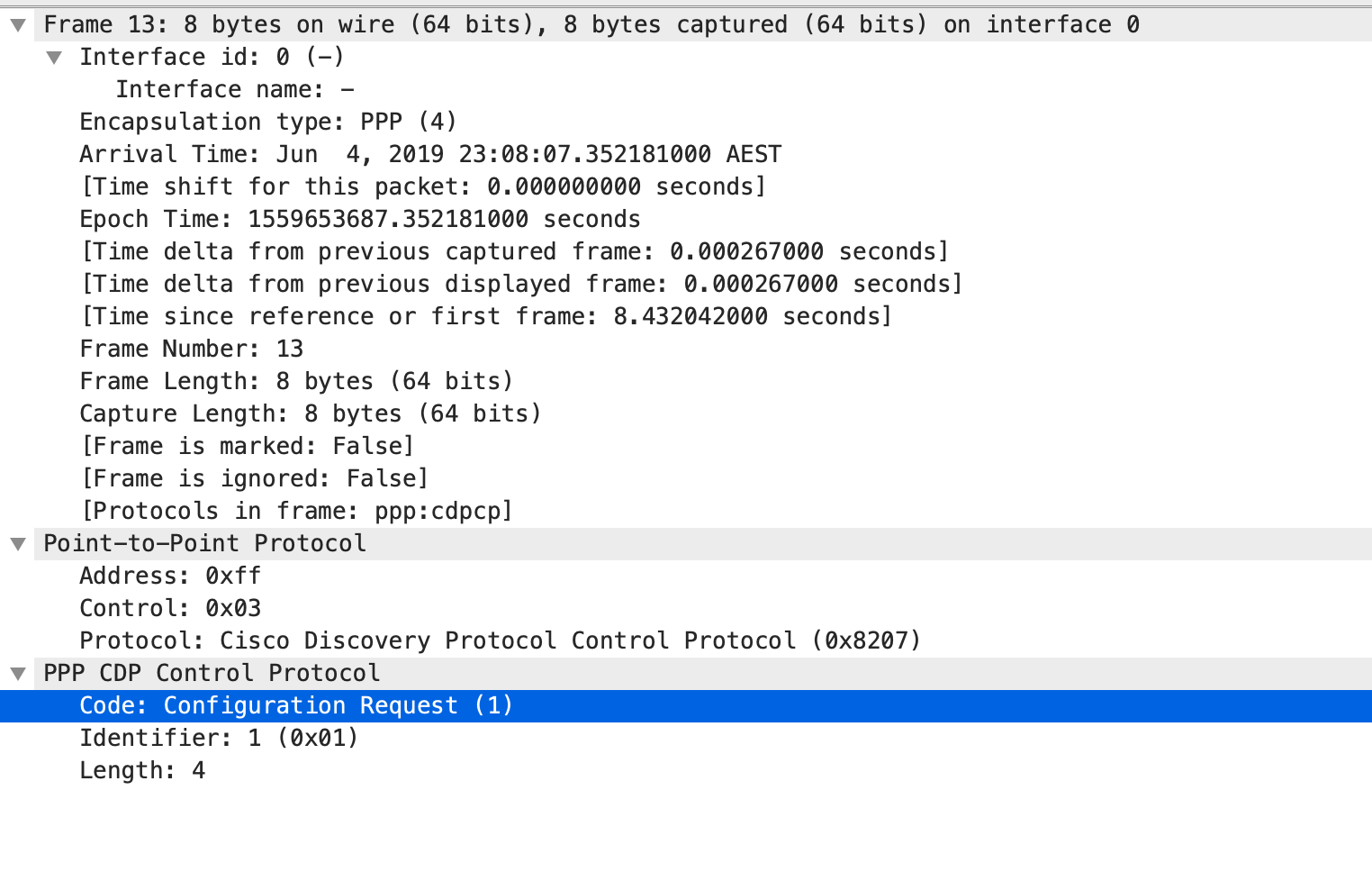
Meanwhile, R1 will also send IPCP and CDPCP Configuration Request to R2. It is interesting to note here that R1 will provide details that its has no IP address,

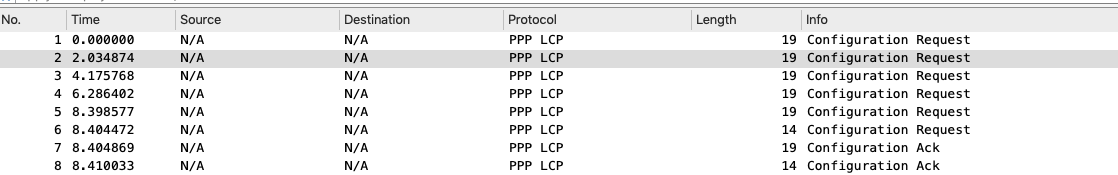
As seen below, both R1 and R2 is exchanging Configuration details. As we know from the configurations, we have assigned an IP address on R2’s serial interface but we have not assigned any to R1 serial port. There was response below from R2 – Configuration-NAK ( or Configuration Negative-Acknowledgment) in which R2 is proposing a new IP to R1 from the IP pool set up on R2.
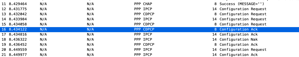
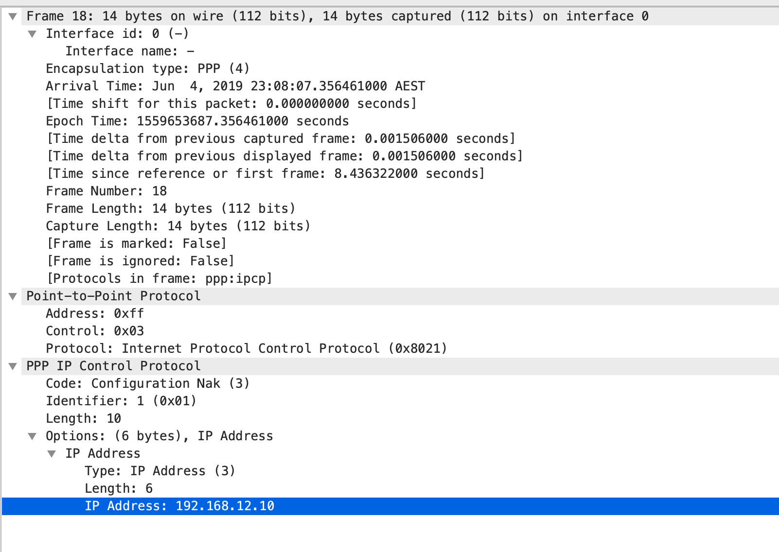
As we could also see that Line 21 shows a Configuration Acknowledgment from R1 and it already shows the IP address that is assigned for its serial interface.

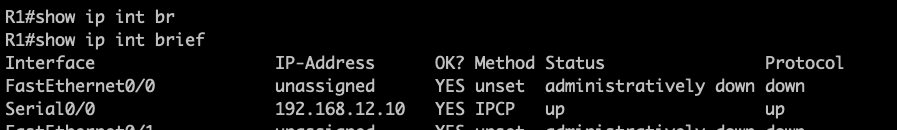
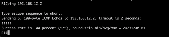
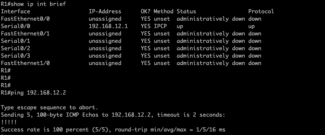
As observed R1, its been assigned with 192.168.12.10 and reachability is established using PPP CHAP One-way Authentications.
########################END OF LAB ############################
Point-to-Point Protocol PAP Two-way Authentication
In my previous post, I have explore how to set up a PPP links using PAP One-way authentications.
For a one-way PAP authentication, the server router is providing the authentication parameters and the client device will need to to match on the username and password that is setup on the server.
For two-way PAP authentication, each participating routers will be challenging each other with the configured usernames and password on each device.
For this LAB, I will be using the same topology as my previous PPP post.

NOTE: I had several occasions in which I have enabled PPP on the interface with my debug enabled as well and this creates some unwanted syslog messages.. I think, its better to shutdown the interface first before configuring PPP , etc.
Let me jump straight to the configurations:
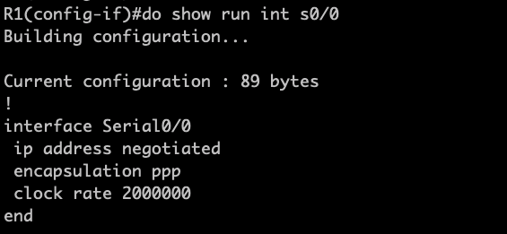
R1#show run int s0/0
Building configuration…
Current configuration : 113 bytes
!
interface Serial0/0
ip address negotiated
encapsulation ppp
clock rate 2000000
ppp authentication pap
end
From the above configs, I will be shutting down Serial 0/0 and configure PPP PAP Authentication.
Step 1. Setting local authentication for R1:
R1(R1(config)#username ccnp password icandoit
Step 2. Enable PAP Authentication
R1(config-if)#ppp authentication ?
chap Challenge Handshake Authentication Protocol (CHAP)
eap Extensible Authentication Protocol (EAP)
ms-chap Microsoft Challenge Handshake Authentication Protocol (MS-CHAP)
ms-chap-v2 Microsoft CHAP Version 2 (MS-CHAP-V2)
pap Password Authentication Protocol (PAP)
R1(config-if)#ppp authentication pap
Step 3. Setup the remote PAP Challenge authentication parameters..
R1(config-if)# ppp pap ?
refuse Refuse to authenticate using PAP
sent-username Set outbound PAP username
wait Wait for caller to authenticate first
R1(config-if)# ppp pap sent-username ccie password go4it
That completes the configurations required in R1:

Let me jump into R2 configurations:


Now, let me enabled the interface in R1:
- There is an Incoming Configuration Request from R2 and LCP message have initiated to used PAP Authentication.

2. R1 have also sent out a Configuration Request to R2 and proposed to used PAP Authentication.

3. R1 send out a Configuration Acknowledgment with R2 :

4. And finally, R1 received a Configuration Acknowledgment from R2 and this completes the LCP Phase.

5. The Authentication Phase in which both routers R1/R2 have agreed on the PAP Authentication parameters.

6. Finally R1 have been assigned with the IP address from the IP pool in R2.
###################### END OF LAB ##############################
Basics of PPP Authentications using PAP – One-Way Authentication
Some notes for PPP Authentication using PAP.
- PAP is sending password in clear-text
Two options to enable PPP Authentications using PAP includes
- One-way PAP Authentications
- Two-way PAP Authentications

On this Post, I’m exploring the configurations of enabling One-way PAP Authentications:
High Level steps below:
1.Set the username and password that will be used for the authentications.
R2(config)#username ccie password go4it
2. Configure under interface mode using the “ppp pap sent-username“command
R2(config-if)#ppp pap sent-username ccie password go4it
PPP: Warning: You have chosen a username/password combination that
is valid for CHAP. This is a potential security hole.
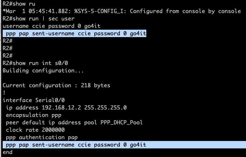
R2(config-if)#do show run int s0/0
Building configuration…
Current configuration : 218 bytes
!
interface Serial0/0
ip address 192.168.12.2 255.255.255.0
encapsulation ppp
peer default ip address pool PPP_DHCP_Pool
clock rate 2000000
ppp authentication pap
ppp pap sent-username ccie password 0 go4it
end
On R1, assigned the same PPP username and password under interface mode:
R1(config)#int s0/0
R1(config-if)#shut
R1(config-if)#ppp pap sent-username ccie password 0 go4it
PPP: Warning: You have chosen a username/password combination that
is valid for CHAP. This is a potential security hole.
R1(config-if)#
Jun 4 05:57:55.547: %LINK-5-CHANGED: Interface Serial0/0, changed state to administratively down
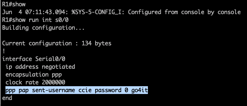
R1(config-if)#do show run int s0/0
Building configuration…
Current configuration : 144 bytes
!
interface Serial0/0
ip address negotiated
encapsulation ppp
shutdown
clock rate 2000000
ppp pap sent-username ccie password 0 go4it
end
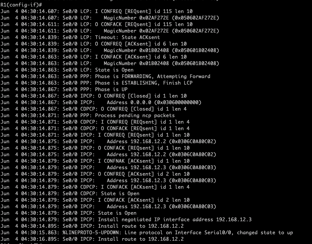
The moment, I have enable the interface , PPP links went through both the LCP and NCP negotiations. We could also see PAP Authentications is being initiated.
R1(config-if)#
Jun 4 07:01:37.946: %LINK-3-UPDOWN: Interface Serial0/0, changed state to up
Jun 4 07:01:37.946: Se0/0 PPP: Using default call direction
Jun 4 07:01:37.950: Se0/0 PPP: Treating connection as a dedicated line
Jun 4 07:01:37.950: Se0/0 PPP: Session handle[B500000E] Session id[14]
Jun 4 07:01:37.950: Se0/0 PPP: Phase is ESTABLISHING, Active Open
Jun 4 07:01:37.950: Se0/0 LCP: O CONFREQ [Closed] id 10 len 10
Jun 4 07:01:37.954: Se0/0 LCP: MagicNumber 0x023ACD40 (0x0506023ACD40)
Jun 4 07:01:37.990: Se0/0 LCP: I CONFREQ [REQsent] id 82 len 14
Jun 4 07:01:37.990: Se0/0 LCP: AuthProto PAP (0x0304C023)
Jun 4 07:01:37.990: Se0/0 LCP: MagicNumber 0x0339D6F4 (0x05060339D6F4)
Jun 4 07:01:37.990: Se0/0 LCP: O CONFACK [REQsent] id 82 len 14
Jun 4 07:01:37.994: Se0/0 LCP: AuthProto PAP (0x0304C023)
Jun 4 07:01:37.994: Se0/0 LCP: MagicNumber 0x0339D6F4 (0x05060339D6F4)
Jun 4 07:01:37.994: Se0/0 LCP: I CONFACK [ACKsent] id 10 len 10
Jun 4 07:01:37.994: Se0/
R1(config-if)#
R1(config-if)#0 LCP: MagicNumber 0x023ACD40 (0x0506023ACD40)
Jun 4 07:01:37.998: Se0/0 LCP: State is Open
Jun 4 07:01:37.998: Se0/0 PPP: Phase is AUTHENTICATING, by the peer
Jun 4 07:01:37.998: Se0/0 PAP: Using hostname from interface PAP
Jun 4 07:01:37.998: Se0/0 PAP: Using password from interface PAP
Jun 4 07:01:37.998: Se0/0 PAP: O AUTH-REQ id 3 len 15 from “ccie”
Jun 4 07:01:38.034: Se0/0 PAP: I AUTH-ACK id 3 len 5
Jun 4 07:01:38.034: Se0/0 PPP: Phase is FORWARDING, Attempting Forward
Jun 4 07:01:38.038: Se0/0 PPP: Queue IPCP code[1] id[1]
Jun 4 07:01:38.038: Se0/0 PPP: Discarded CDPCP code[1] id[1]
Jun 4 07:01:38.038: Se0/0 PPP: Phase is ESTABLISHING, Finish LCP
Jun 4 07:01:38.042: Se0/0 PPP: Phase is UP
Jun 4 07:01:38.042: Se0/0 IPCP: O CONFREQ [Closed] id 1 len 10
Jun 4 07:01:38.042: Se0/0 IPCP: Address 0.0.0.0 (0x030600000000)
Jun 4 07:01:38.042: Se0/0 CDPCP: O CONFREQ [Closed] id 1 len 4
Jun 4 07:01:38.046: Se0/0 PPP: Process pending ncp packets
Jun 4 07:01:38.046: Se0/0 IPCP: Redirect packet to Se0/0
Jun 4 07:01:38.046: Se0/0 IPCP: I CONFREQ [REQsent] id 1 len 10
Jun 4 07:01:38.046: Se0/0 IPCP: Address 192.168.12.2 (0x0306C0A80C02)
Jun 4 07:01:38.046: Se0/0 IPCP: O CONFACK [REQsent] id 1 len 10
Jun 4 07:01:38.046: Se0/0 IPCP: Address 192.168.12.2 (0x0306C0A80C02)
Jun 4 07:01:38.050: Se0/0 CDPCP: I CONFACK [REQsent] id 1 len 4
Jun 4 07:01:38.054: Se0/0 IPCP: I CONFNAK [ACKsent] id 1 len 10
Jun 4 07:01:38.054: Se0/0 IPCP: Address 192.168.12.3 (0x0306C0A80C03)
Jun 4 07:01:38.054: Se0/0 IPCP: O CONFREQ [ACKsent] id 2 len 10
Jun 4 07:01:38.054: Se0/0 IPCP: Address 192.168.12.3 (0x0306C0A80C03)
Jun 4 07:01:38.078: Se0/0 IPCP: I CONFACK [ACKsent] id 2 len 10
Jun 4 07:01:38.078: Se0/0 IPCP: Address 192.168.12.3 (0x0306C0A80C03)
Jun 4 07:01:38.078: Se0/0 IPCP: State is Open
Jun 4 07:01:38.082: Se0/0 IPCP: Install negotiated IP interface address 192.168.12.3
Jun 4 07:01:38.094: Se0/0 IPCP: Install route to 192.168.12.2
Jun 4 07:01:39.038: %LINEPROTO-5-UPDOWN: Line protocol on Interface Serial0/0, changed state to up
Jun 4 07:01:40.022: Se0/0 CDPCP: Timeout: State ACKrcvd
Jun 4 07:01:40.022: Se0/0 CDPCP: O CONFREQ [ACKrcvd] id 2 len 4
Jun 4 07:01:40.042: Se0/0 CDPCP: I CONFACK [REQsent] id 2 len 4
Jun 4 07:01:40.094: Se0/0 IPCP: Install route to 192.168.12.2
Jun 4 07:01:41.258: Se0/0 CDPCP: I CONFREQ [ACKrcvd] id 2 len 4
Jun 4 07:01:41.258: Se0/0 CDPCP: O CONFACK [ACKrcvd] id 2 len 4
Jun 4 07:01:41.262: Se0/0 CDPCP: State is Open
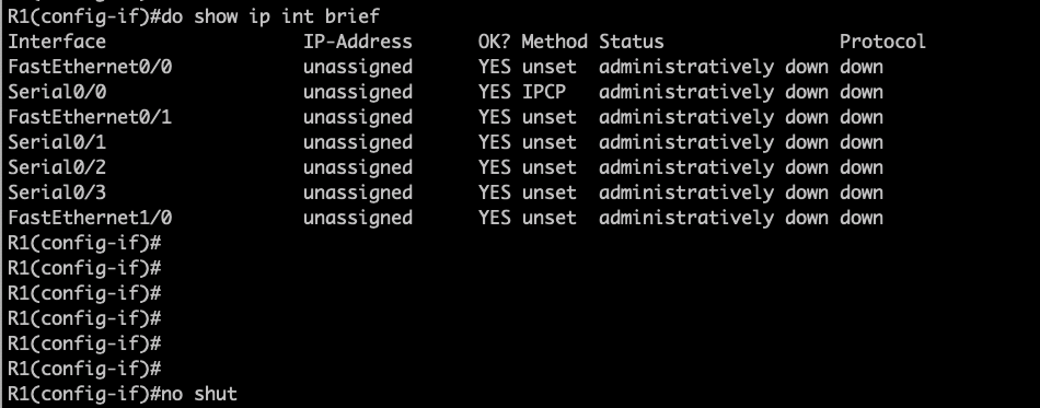
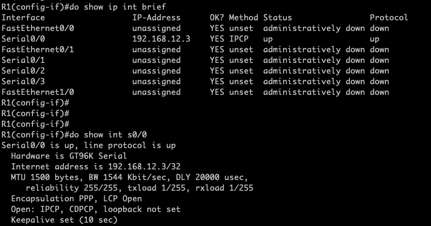
R1(config-if)#do show ip int br
Interface IP-Address OK? Method Status Protocol
FastEthernet0/0 unassigned YES unset administratively down down
Serial0/0 192.168.12.3 YES IPCP up up
FastEthernet0/1 unassigned YES unset administratively down down
Serial0/1 unassigned YES unset administratively down down
Serial0/2 unassigned YES unset administratively down down
Serial0/3 unassigned YES unset administratively down down
FastEthernet1/0 unassigned YES unset administratively down down
R1(config-if)#
R1(config-if)#
R1(config-if)#do show int s0/0
Serial0/0 is up, line protocol is up
Hardware is GT96K Serial
Internet address is 192.168.12.3/32
MTU 1500 bytes, BW 1544 Kbit/sec, DLY 20000 usec,
reliability 255/255, txload 1/255, rxload 1/255
Encapsulation PPP, LCP Open
Open: IPCP, CDPCP, loopback not set
In summary, in order to enable one-way PAP authentication, the router controlling the PPP sessions should set a username and password that will be used for the establishing the PPP sessions.
#################### END OF LAB #################################
Basics of Point-to-Point Protocols
As I’m looking at the Blueprints for the exam, these particular layer 2 WAN protocol is still included. Thus, having some knowledge of PPP is still necessary as I can see this are being ask in the Cisco exams.
For this particular post, I will be exploring the various options on how to enable PPP. As I transitions from using GNS3 to VIRL, I just realised while building my labs in VIRL that Serial interface interface is not supported thus defaulting to GNS3 to check how PPP works.
The scope is only to explore the various options of enabling PPP. Password Authentications will be explored on another post.

As a quick background , PPP have to consider the following phases and a matching parameters on each phases must be agreed in order for PPP sessions to be up.
- Link Control Protocols ( LCP)
- Authentication which is an optional parameter
- Network Control Protocol (NCP)
On LCP negotiations, there were 4 control messages that will be shown when a PPP debug is enable. This control messages includes:
- Configuration request
- Configuration reject
- Configuration-NAK or Negative acknowledgment
- Configuration-Acknowledgement
The various options of enabling PPP includes:
- Manual assigning of IP address on the interface
- Negotiated (meaning the peer will be assigning an IP address for the remote device)
- Using IP pool
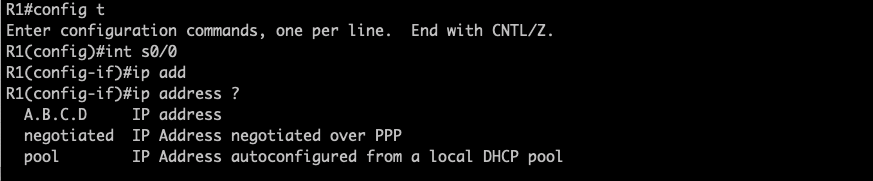
Option 1: Manual assignment of IP address
R1 Configurations:
R2 Configurations:

So both R1 and R2 is assigned with the IP address with PPP encapsulations enable on both device. I have disabled the Serial interface in R1 and have enabled debug to check the LCP/NCP negotiations.
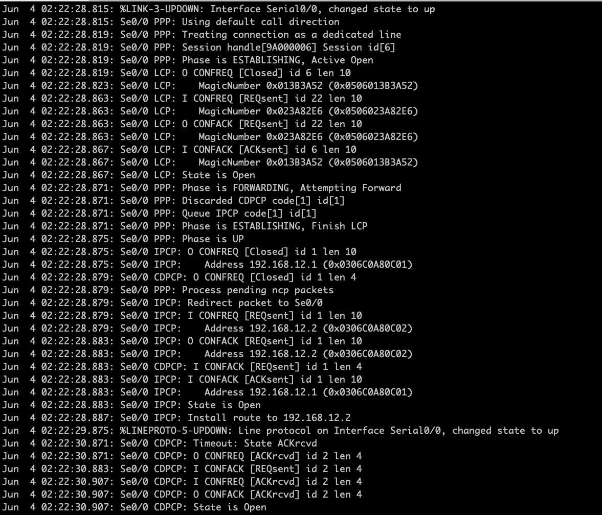
Jun 4 02:22:28.815: %LINK-3-UPDOWN: Interface Serial0/0, changed state to up
Jun 4 02:22:28.815: Se0/0 PPP: Using default call direction
Jun 4 02:22:28.819: Se0/0 PPP: Treating connection as a dedicated line
Jun 4 02:22:28.819: Se0/0 PPP: Session handle[9A000006] Session id[6]
Jun 4 02:22:28.819: Se0/0 PPP: Phase is ESTABLISHING, Active Open
Jun 4 02:22:28.819: Se0/0 LCP: O CONFREQ [Closed] id 6 len 10
Jun 4 02:22:28.823: Se0/0 LCP: MagicNumber 0x013B3A52 (0x0506013B3A52)
Jun 4 02:22:28.863: Se0/0 LCP: I CONFREQ [REQsent] id 22 len 10
Jun 4 02:22:28.863: Se0/0 LCP: MagicNumber 0x023A82E6 (0x0506023A82E6)
Jun 4 02:22:28.863: Se0/0 LCP: O CONFACK [REQsent] id 22 len 10
Jun 4 02:22:28.863: Se0/0 LCP: MagicNumber 0x023A82E6 (0x0506023A82E6)
Jun 4 02:22:28.867: Se0/0 LCP: I CONFACK [ACKsent] id 6 len 10
Jun 4 02:22:28.867: Se0/0 LCP: MagicNumber 0x013B3A52 (0x0506013B3A52)
Jun 4 02:22:28.867: Se0/0 LCP: State is Open
Jun 4 02:22:28.871: Se0/0 PPP: Phase is FORWARDING, Attempting Forward
Jun 4 02:22:28.871: Se0/0 PPP: Discarded CDPCP code[1] id[1]
Jun 4 02:22:28.871: Se0/0 PPP: Queue IPCP code[1] id[1]
Jun 4 02:22:28.871: Se0/0 PPP: Phase is ESTABLISHING, Finish LCP
Jun 4 02:22:28.875: Se0/0 PPP: Phase is UP
Jun 4 02:22:28.875: Se0/0 IPCP: O CONFREQ [Closed] id 1 len 10
Jun 4 02:22:28.875: Se0/0 IPCP: Address 192.168.12.1 (0x0306C0A80C01)
Jun 4 02:22:28.879: Se0/0 CDPCP: O CONFREQ [Closed] id 1 len 4
Jun 4 02:22:28.879: Se0/0 PPP: Process pending ncp packets
Jun 4 02:22:28.879: Se0/0 IPCP: Redirect packet to Se0/0
Jun 4 02:22:28.879: Se0/0 IPCP: I CONFREQ [REQsent] id 1 len 10
Jun 4 02:22:28.879: Se0/0 IPCP: Address 192.168.12.2 (0x0306C0A80C02)
Jun 4 02:22:28.883: Se0/0 IPCP: O CONFACK [REQsent] id 1 len 10
Jun 4 02:22:28.883: Se0/0 IPCP: Address 192.168.12.2 (0x0306C0A80C02)
Jun 4 02:22:28.883: Se0/0 CDPCP: I CONFACK [REQsent] id 1 len 4
Jun 4 02:22:28.883: Se0/0 IPCP: I CONFACK [ACKsent] id 1 len 10
Jun 4 02:22:28.883: Se0/0 IPCP: Address 192.168.12.1 (0x0306C0A80C01)
Jun 4 02:22:28.883: Se0/0 IPCP: State is Open
Jun 4 02:22:28.887: Se0/0 IPCP: Install route to 192.168.12.2
Jun 4 02:22:29.875: %LINEPROTO-5-UPDOWN: Line protocol on Interface Serial0/0, changed state to up
Jun 4 02:22:30.871: Se0/0 CDPCP: Timeout: State ACKrcvd
Jun 4 02:22:30.871: Se0/0 CDPCP: O CONFREQ [ACKrcvd] id 2 len 4
Jun 4 02:22:30.883: Se0/0 CDPCP: I CONFACK [REQsent] id 2 len 4
Jun 4 02:22:30.907: Se0/0 CDPCP: I CONFREQ [ACKrcvd] id 2 len 4
Jun 4 02:22:30.907: Se0/0 CDPCP: O CONFACK [ACKrcvd] id 2 len 4
Jun 4 02:22:30.907: Se0/0 CDPCP: State is Open
Dissecting the PPP Negotiations as follows:
LCP Phase
- The moment I enabled the interface on R1, we could see the first Phase – ESTABLISHMENT PHASE
- R1 is sending an outgoing Configuration Request (O means outgoing) which is tracked with an id 6 and it also received an incoming ( I means Incoming) Configuration Request from R2 with an id 22.
- R1 have sent out a Configuration ACK to R2 in response to the Configurations Request (id 22)
- R1 has also received an Incoming Configuration ACK from R2.
- As both have matching parameters ( simple because we did not set any password authentications) , LCP state is OPEN
NCP PHASE
- Thus PPP have moved to the second phase is the FORWARDING PHASE.
- Network Control Protocol (NCP) uses CDP ( in PPP it shows as CDPCP) to learned about the neighboring devices and it uses another protocol called IPCP to negotiates or learned about the IP address.
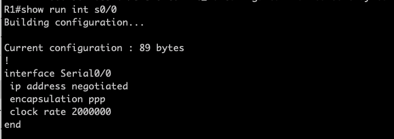
OPTION 2. Using “ip address negotiated”
R2 configurations.
The peer default ip address is used to set the IP address of the peer router.
Configuring R1:
So basically, in order for R1 to obtain an IP address, the “ip address negotiated” is configure under interface mode. As notice there is no IP address assigned on Serial interface.

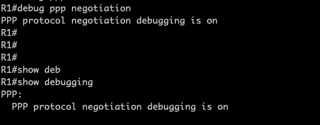
Upon assigning the statement “ip address negotiated on R1”, PPP negotiations started with IPCP messages .
I’m running a “debug ppp negotiation ” on R1 to observed the negotiations.
From the output above, the IP address 192.168.12.1 is installed on the serial interface of R1 and PPP encapsulations is enabled.
OPTIONS 3. USING IP POOL
High level steps:
- Configure an IP pool from which the interface IP address will be allocated. In my example, I’m going to configure this on R2.
- On R2, Set the peer default ip address to the ip pool created
- On R1, keep the ip address negotiated
For R1, I have set “ip address negotiated”
In order to assigned the address on R1, I have to bounce the links between R1 and R2 …What I notice is that when I only shutdown the serial link on R1, it still inherits the previous IP address assigned. This could be observed on this debug output,


Upon unshutting the serial interface in R1, I could start observing PPP negotiations again and the IP pool address which I have set up in R2 were assigned on R1.
###############END OF LAB ###############################
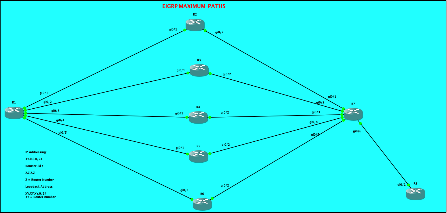
EIGRP Maximum-Paths and Variance
By default, EIGRP have a maximum of four equal cost path for load-balancing traffic. But what if we have more than 4 paths available? EIGRP have this features called “maximum-paths”under EIGRP process which can increased the paths up to 32 equal cost path links.
I’m going to explore this behaviour with 5 equal cost path. For this lab, my task are as follows:
Configure EIGRP on all routers. Conditions as follows:
a. Used network statement “0.0.0.0”on all routers
b. Disable auto-summary
c. Disable all other EIGRP metrics except for delay
Scenario # 1:
Allow all 5 paths between R1 and R7 for load-balancing
Scenario # 2:
Used Paths R1<–> R3<–>R7 and R1<—>R5<—> R7 to become Feasible Successor.
Scenario # 3:
Update the delays so that the feasible successor will do unequal-load balancing with traffic ratio of 5:1 (Successor:Feasible Successor)
| CONFIGURATIONS R1: R1#show ip int brief Interface IP-Address OK? Method Status Protocol GigabitEthernet0/0 10.255.0.233 YES NVRAM administratively down down GigabitEthernet0/1 12.0.0.1 YES NVRAM up up GigabitEthernet0/2 13.0.0.1 YES NVRAM up up GigabitEthernet0/3 14.0.0.1 YES NVRAM up up GigabitEthernet0/4 15.0.0.1 YES NVRAM up up GigabitEthernet0/5 16.0.0.1 YES NVRAM up up Loopback0 1.1.1.1 YES NVRAM up up R1#show run | sec eigrp router eigrp 100 metric weights 0 0 0 1 0 0 network 0.0.0.0 eigrp router-id 1.1.1.1 |
| R2: R2#show ip int brief Interface IP-Address OK? Method Status Protocol GigabitEthernet0/0 10.255.0.234 YES NVRAM administratively down down GigabitEthernet0/1 12.0.0.2 YES NVRAM up up GigabitEthernet0/2 27.0.0.2 YES NVRAM up up R2#show run | sec eigrp router eigrp 100 metric weights 0 0 0 1 0 0 network 0.0.0.0 eigrp router-id 2.2.2.2 |
| R3: R3#show ip int brief Interface IP-Address OK? Method Status Protocol GigabitEthernet0/0 10.255.0.235 YES NVRAM administratively down down GigabitEthernet0/1 13.0.0.3 YES NVRAM up up GigabitEthernet0/2 37.0.0.3 YES NVRAM up up R3#show run | sec eig router eigrp 100 metric weights 0 0 0 1 0 0 network 0.0.0.0 eigrp router-id 3.3.3.3 |
| R4: R4#show ip int brief Interface IP-Address OK? Method Status Protocol GigabitEthernet0/0 10.255.0.236 YES NVRAM administratively down down GigabitEthernet0/1 14.0.0.4 YES NVRAM up up GigabitEthernet0/2 47.0.0.4 YES NVRAM up up R4#sho run | sec eigrp router eigrp 100 metric weights 0 0 0 1 0 0 network 0.0.0.0 eigrp router-id 4.4.4.4 |
| R5: R5#show ip int brief Interface IP-Address OK? Method Status Protocol GigabitEthernet0/0 10.255.0.237 YES NVRAM administratively down down GigabitEthernet0/1 15.0.0.5 YES NVRAM up up GigabitEthernet0/2 57.0.0.5 YES NVRAM up up R5#show run | sec eigrp router eigrp 100 metric weights 0 0 0 1 0 0 network 0.0.0.0 eigrp router-id 5.5.5.5 |
| R6: R6#show ip int brief Interface IP-Address OK? Method Status Protocol GigabitEthernet0/0 10.255.0.238 YES NVRAM administratively down down GigabitEthernet0/1 16.0.0.6 YES NVRAM up up GigabitEthernet0/2 67.0.0.6 YES NVRAM up up R6#show run | sec eigrp router eigrp 100 metric weights 0 0 0 1 0 0 network 0.0.0.0 eigrp router-id 6.6.6.6 |
| R7: R7#show ip int brief Interface IP-Address OK? Method Status Protocol GigabitEthernet0/0 10.255.0.239 YES NVRAM administratively down down GigabitEthernet0/1 27.0.0.7 YES NVRAM up up GigabitEthernet0/2 37.0.0.7 YES NVRAM up up GigabitEthernet0/3 47.0.0.7 YES NVRAM up up GigabitEthernet0/4 57.0.0.7 YES NVRAM up up GigabitEthernet0/5 67.0.0.7 YES NVRAM up up GigabitEthernet0/6 68.0.0.7 YES NVRAM up up R7#show run | sec eigrp router eigrp 100 metric weights 0 0 0 1 0 0 network 0.0.0.0 eigrp router-id 7.7.7.7 |
| R8: R8#show ip int brief Interface IP-Address OK? Method Status Protocol GigabitEthernet0/0 10.255.0.240 YES NVRAM administratively down down GigabitEthernet0/1 68.0.0.8 YES NVRAM up up Loopback8 8.8.8.8 YES NVRAM up up R8#show run | sec eigrp router eigrp 100 metric weights 0 0 0 1 0 0 network 0.0.0.0 eigrp router-id 8.8.8.8 R8# |
From R1 EIGRP topology, it shows 4 successors towards the prefix 8.8.8.8/32
| R1#show ip eigrp topology EIGRP-IPv4 Topology Table for AS(100)/ID(1.1.1.1) Codes: P – Passive, A – Active, U – Update, Q – Query, R – Reply, r – reply Status, s – sia Status P 14.0.0.0/24, 1 successors, FD is 256 via Connected, GigabitEthernet0/3 P 57.0.0.0/24, 1 successors, FD is 512 via 15.0.0.5 (512/256), GigabitEthernet0/4 P 13.0.0.0/24, 1 successors, FD is 256 via Connected, GigabitEthernet0/2 P 15.0.0.0/24, 1 successors, FD is 256 via Connected, GigabitEthernet0/4 P 12.0.0.0/24, 1 successors, FD is 256 via Connected, GigabitEthernet0/1 P 8.8.8.8/32, 4 successors, FD is 128768 via 12.0.0.2 (128768/128512), GigabitEthernet0/1 via 13.0.0.3 (128768/128512), GigabitEthernet0/2 via 14.0.0.4 (128768/128512), GigabitEthernet0/3 via 15.0.0.5 (128768/128512), GigabitEthernet0/4 via 16.0.0.6 (128768/128512), GigabitEthernet0/5 |
We can quickly check the routing table of R1:
| R1#show ip route eigrp | sec 8.8.8.8 D 8.8.8.8 [90/128768] via 15.0.0.5, 03:59:07, GigabitEthernet0/4 [90/128768] via 14.0.0.4, 03:59:07, GigabitEthernet0/3 [90/128768] via 13.0.0.3, 03:59:07, GigabitEthernet0/2 [90/128768] via 12.0.0.2, 03:59:07, GigabitEthernet0/1 27.0.0.0/24 is subnetted, 1 subnets So R1 routing table have installed 4 with equal metrics, though, we can see 5 equal cost-path on the topology table. |
Let’s enable maximum-path and set the value to 5.
| R1#show ip eigrp topology | sec 8.8.8.8 P 8.8.8.8/32, 5 successors, FD is 128768 via 12.0.0.2 (128768/128512), GigabitEthernet0/1 via 13.0.0.3 (128768/128512), GigabitEthernet0/2 via 14.0.0.4 (128768/128512), GigabitEthernet0/3 via 15.0.0.5 (128768/128512), GigabitEthernet0/4 via 16.0.0.6 (128768/128512), GigabitEthernet0/5 R1# As observed, the total successors have increased from 4 to 5. |
What about the routing table of R1?
| R1#show ip route eigrp | sec 8.8.8.8 D 8.8.8.8 [90/128768] via 16.0.0.6, 00:01:46, GigabitEthernet0/5 [90/128768] via 15.0.0.5, 00:01:46, GigabitEthernet0/4 [90/128768] via 14.0.0.4, 00:01:46, GigabitEthernet0/3 [90/128768] via 13.0.0.3, 00:01:46, GigabitEthernet0/2 [90/128768] via 12.0.0.2, 00:01:46, GigabitEthernet0/1 27.0.0.0/24 is subnetted, 1 subnets R1# So by this time we could see that there are 5 available paths on R1’s routing table towards 8.8.8.8/32 This completes the objective for Scenario # 1. — COMPLETED |
Let me modify the delay on all the routers and set it into 3000 microseconds and will be tweaking the delay in order to make R3 and R5 as feasible successors.
| Command: config t int gi0/X where X refers to all the active interfaces.. delay 300 R1: R1#show interfaces gigabitEthernet 0/1 | inc 3000 MTU 1500 bytes, BW 1000000 Kbit/sec, DLY 3000 usec, R1#show interfaces gigabitEthernet 0/2 | inc 3000 MTU 1500 bytes, BW 1000000 Kbit/sec, DLY 3000 usec, R1#show interfaces gigabitEthernet 0/3 | inc 3000 MTU 1500 bytes, BW 1000000 Kbit/sec, DLY 3000 usec, R1#show interfaces gigabitEthernet 0/4 | inc 3000 MTU 1500 bytes, BW 1000000 Kbit/sec, DLY 3000 usec, R1#show interfaces gigabitEthernet 0/5 | inc 3000 MTU 1500 bytes, BW 1000000 Kbit/sec, DLY 3000 usec, R1# R2: R2#show int gigabitEthernet 0/1 | inc 3000 MTU 1500 bytes, BW 1000000 Kbit/sec, DLY 3000 usec, R2# R2#show int gigabitEthernet 0/2 | inc 3000 MTU 1500 bytes, BW 1000000 Kbit/sec, DLY 3000 usec, R2# R3: R3#show interfaces gigabitEthernet 0/1 | inc 3000 MTU 1500 bytes, BW 1000000 Kbit/sec, DLY 3000 usec, R3#show interfaces gigabitEthernet 0/2 | inc 3000 MTU 1500 bytes, BW 1000000 Kbit/sec, DLY 3000 usec, R3# R4: R4#show interfaces gigabitEthernet 0/1 | inc 3000 MTU 1500 bytes, BW 1000000 Kbit/sec, DLY 3000 usec, R4#show interfaces gigabitEthernet 0/2 | inc 3000 MTU 1500 bytes, BW 1000000 Kbit/sec, DLY 3000 usec, R4# R5: R5#show int gigabitEthernet 0/1 | inc 3000 MTU 1500 bytes, BW 1000000 Kbit/sec, DLY 3000 usec, R5#show int gigabitEthernet 0/2 | inc 3000 MTU 1500 bytes, BW 1000000 Kbit/sec, DLY 3000 usec, R5# R6: R6#show int gigabitEthernet 0/1 | inc 3000 MTU 1500 bytes, BW 1000000 Kbit/sec, DLY 3000 usec, R6#show int gigabitEthernet 0/2 | inc 3000 MTU 1500 bytes, BW 1000000 Kbit/sec, DLY 3000 usec, R6# R7: R7#show int gigabitEthernet 0/1 | inc 3000 MTU 1500 bytes, BW 1000000 Kbit/sec, DLY 3000 usec, R7#show int gigabitEthernet 0/2 | inc 3000 MTU 1500 bytes, BW 1000000 Kbit/sec, DLY 3000 usec, R7#show int gigabitEthernet 0/3 | inc 3000 MTU 1500 bytes, BW 1000000 Kbit/sec, DLY 3000 usec, R7#show int gigabitEthernet 0/4 | inc 3000 MTU 1500 bytes, BW 1000000 Kbit/sec, DLY 3000 usec, R7#show int gigabitEthernet 0/5 | inc 3000 MTU 1500 bytes, BW 1000000 Kbit/sec, DLY 3000 usec, R7# R8: R8#show int gigabitEthernet 0/1 | inc 3000 MTU 1500 bytes, BW 1000000 Kbit/sec, DLY 3000 usec, R8# |
Now me change the Delay on the Links between R1 –> R3 –>R7 and also R1 –> R5 –>R7
| I have changed the Delay to 500 on R1, R3, R5 and R7. R1#show run int gigabitEthernet 0/2 Building configuration… Current configuration : 124 bytes ! interface GigabitEthernet0/2 ip address 13.0.0.1 255.255.255.0 delay 500 duplex auto speed auto media-type rj45 end R1#show run int gigabitEthernet 0/4 Building configuration… Current configuration : 124 bytes ! interface GigabitEthernet0/4 ip address 15.0.0.1 255.255.255.0 delay 500 duplex auto speed auto media-type rj45 end R1# R3#show run int gigabitEthernet 0/1 Building configuration… Current configuration : 124 bytes ! interface GigabitEthernet0/1 ip address 13.0.0.2 255.255.255.0 delay 500 duplex auto speed auto media-type rj45 end R3#show run int gigabitEthernet 0/2 Building configuration… Current configuration : 124 bytes ! interface GigabitEthernet0/2 ip address 37.0.0.2 255.255.255.0 delay 500 duplex auto speed auto media-type rj45 end R5#show running-config int gigabitEthernet 0/1 Building configuration… Current configuration : 124 bytes ! interface GigabitEthernet0/1 ip address 15.0.0.2 255.255.255.0 delay 500 duplex auto speed auto media-type rj45 end R5#show running-config int gigabitEthernet 0/2 Building configuration… Current configuration : 124 bytes ! interface GigabitEthernet0/2 ip address 57.0.0.2 255.255.255.0 delay 500 duplex auto speed auto media-type rj45 end R5# R7#show run int gigabitEthernet 0/2 Building configuration… Current configuration : 124 bytes ! interface GigabitEthernet0/2 ip address 37.0.0.7 255.255.255.0 delay 500 duplex auto speed auto media-type rj45 end R7#show run int gigabitEthernet 0/4 Building configuration… Current configuration : 124 bytes ! interface GigabitEthernet0/4 ip address 57.0.0.7 255.255.255.0 delay 500 duplex auto speed auto media-type rj45 end |
Now let check the topology table and routing table of R1..
| R1#show ip eigrp topology all-links | sec 8.8.8.8 P 8.8.8.8/32, 5 successors, FD is 307200, serno 153 via 12.0.0.2 (358400/281600), GigabitEthernet0/1 via 14.0.0.2 (358400/281600), GigabitEthernet0/3 via 16.0.0.2 (358400/281600), GigabitEthernet0/5 via 13.0.0.2 (460800/332800), GigabitEthernet0/2 via 15.0.0.2 (460800/332800), GigabitEthernet0/4 R1# So as observed above, there were 3 successors ( via R2, R4, and R6) which have a lower Feasible Distance than R3 and R5 and as part of the objective for Scenario # 2, we wanted R3 and R5 to be a Feasible Successors. NOTE: It is interesting to see that the eigrp topology mentioned 5 successors, though if we look at the Feasible distance via R3 and R5, it’s higher as compared to the feasible distance via R2, R4 and R6. Does R3 and R5 meets the Feasibility Conditions? Remember the Feasibility Conditions? Ït states that in order to become a Feasible Successor, the Advertised Distance of a candidate feasible successor should be less than the Feasible Distance of the Successor. A.D. ( Feasible Successor) < F.D. ( Successor) So both R3 and R5 have the advertise distance of 332800 towards R1. Take note that 332800 was the Feasible Distance of R3 and R5 towards the prefix 8.8.8.8/32 and this is reported or advertised to R1. So R1 have taken this values as Advertise distance on its topology table from both R3 and R5. R3#show ip eigrp topology | sec 8.8.8.8 P 8.8.8.8/32, 1 successors, FD is 230400 via 37.0.0.7 (332800/204800), GigabitEthernet0/2 R3# R5#sho ip eigrp topology | sec 8.8.8.8 P 8.8.8.8/32, 1 successors, FD is 230400 via 57.0.0.7 (332800/204800), GigabitEthernet0/2 R5# R1 Feasible Distance with respect to R3 and R5 is 460800. R1 Feasible Distance with respect to R2, R4 and R6 is 358400. So with this complex EIGRP metrics computations, we already know that R2, R4 and R6 will be the Successors towards 8.8.8.8/32 while R3 and R5 which meets the Feasibility Conditions will become Feasible Successors. So therefore, we would expect R2, R4 and R6 will be installed on R1 routing table as the equal cost paths towards 8.8.8.8/32. R1#show ip route eigrp | sec 8.8.8.8 D 8.8.8.8 [90/358400] via 16.0.0.2, 00:00:04, GigabitEthernet0/5 [90/358400] via 14.0.0.2, 00:00:04, GigabitEthernet0/3 [90/358400] via 12.0.0.2, 00:00:04, GigabitEthernet0/1 27.0.0.0/24 is subnetted, 1 subnets R1# But as we can see from R1’s routing table, the Feasible Successor is not added yet. So this be need to enable Unequal Cost Path Load Balancing so that it will be installed on R1’s routing table. That requirements will be completed on Scenario # 3. This completes the second scenario for this lab. – COMPLETED |
For the third scenario, I will need to update the variance in order to have an unequal cost path load balancing. Meaning, I would expect that R3 and R5 paths will also be installed on R1’s routing table.
| So what is the rule for Unequal Cost Path Load Balancing? “The rule states that the Feasible Distance of Feasible Successor should be less than the Feasible Distance of a Successor times a variance multiplier.” Mathematically, F.D. ( Feasible Successor) < F.D. ( Successor) * Variance So variance is important in order to configure Unequal Cost Path Load Balancing in EIGRP. This can be applied under EIGRP process as shown below, R1(config)#router eigrp 100 R1(config-router)#variance ? <1-128> Metric variance multiplier R1(config-router)#variance So from R1 perspective, the Feasible Distance of the Feasible Successors ( R3 and R5) is 460800 while the Feasible Distance of Successors ( R2, R4 and R6) is 358400. So mathematically, I can set a variance of 2 in order to meet the conditions. 460800 < 358400 * 2 460800 < 716800 So what I did is I have multiplied 358400 * 2 = 716800 R1(config)#router eigrp 100 R1(config-router)#variance 2 Now, from R1 routing table , it already shows 5 paths to reach 8.8.8.8/32. Variance of 2 have allowed this happen though as observed those 5 paths have indicated the feasible distance are not the same. R1#show ip route eigrp | sec 8.8.8.8 D 8.8.8.8 [90/358400] via 16.0.0.2, 00:00:55, GigabitEthernet0/5 [90/460800] via 15.0.0.2, 00:00:55, GigabitEthernet0/4 [90/358400] via 14.0.0.2, 00:00:55, GigabitEthernet0/3 [90/460800] via 13.0.0.2, 00:00:55, GigabitEthernet0/2 [90/358400] via 12.0.0.2, 00:00:55, GigabitEthernet0/1 27.0.0.0/24 is subnetted, 1 subnets R1# So I think we are done on the Non-Equal Cost Path configurations but the Scenario # 3 objective is to have as much as 5 times amount of traffic for R2, R4 and R6 as compared to the amount of traffic carried by R3 and R5. So The next action that we can do is to play with the the variance or with the delay on the interface. So what will gonna happen if I will increased the variance to 25…. R1(config)#router eigrp 100 R1(config-router)#variance 25 R1(config-router)#^Z R1#sh *Jun 1 14:52:33.652: %SYS-5-CONFIG_I: Configured from console by cons R1#show ip eigrp topology | sec 8.8.8.8 P 8.8.8.8/32, 5 successors, FD is 358400 via 12.0.0.2 (358400/281600), GigabitEthernet0/1 via 14.0.0.2 (358400/281600), GigabitEthernet0/3 via 16.0.0.2 (358400/281600), GigabitEthernet0/5 via 13.0.0.2 (460800/332800), GigabitEthernet0/2 via 15.0.0.2 (460800/332800), GigabitEthernet0/4 R1# As observed increasing the variance to 25 does not change the Feasible distance… So that means, I can play around with the delay. So if we look at the Metrics calculations, Delay is propotional to the overall metrics, meaning increasing the delay would mean an increased on the metrics. Now since, I wanted to have an amount of traffic of 5 times as much for R2, R4 and R6, it means that I would need to have a feasible distance for R3 and R5 which is 5 times the current feasible distance of R2, R4, and R6…Does this makes since? Lets check the current traffic share of all the 5 routers from R1’s perspective.. R1#show ip route 8.8.8.8 Routing entry for 8.8.8.8/32 Known via “eigrp 100”, distance 90, metric 358400, type internal Redistributing via eigrp 100 Last update from 14.0.0.2 on GigabitEthernet0/3, 00:06:15 ago Routing Descriptor Blocks: 16.0.0.2, from 16.0.0.2, 00:06:15 ago, via GigabitEthernet0/5 Route metric is 358400, traffic share count is 240 Total delay is 14000 microseconds, minimum bandwidth is 1000000 Kbit Reliability 252/255, minimum MTU 1500 bytes Loading 1/255, Hops 3 15.0.0.2, from 15.0.0.2, 00:06:15 ago, via GigabitEthernet0/4 Route metric is 460800, traffic share count is 187 Total delay is 18000 microseconds, minimum bandwidth is 1000000 Kbit Reliability 253/255, minimum MTU 1500 bytes Loading 1/255, Hops 3 14.0.0.2, from 14.0.0.2, 00:06:15 ago, via GigabitEthernet0/3 Route metric is 358400, traffic share count is 240 Total delay is 14000 microseconds, minimum bandwidth is 1000000 Kbit Reliability 253/255, minimum MTU 1500 bytes Loading 1/255, Hops 3 13.0.0.2, from 13.0.0.2, 00:06:15 ago, via GigabitEthernet0/2 Route metric is 460800, traffic share count is 187 Total delay is 18000 microseconds, minimum bandwidth is 1000000 Kbit Reliability 253/255, minimum MTU 1500 bytes Loading 1/255, Hops 3 12.0.0.2, from 12.0.0.2, 00:06:15 ago, via GigabitEthernet0/1 Route metric is 358400, traffic share count is 240 Total delay is 14000 microseconds, minimum bandwidth is 1000000 Kbit Reliability 251/255, minimum MTU 1500 bytes Loading 1/255, Hops 3 R1# As can be seen above, the traffic shares of R2, R4 and R6 is 240 while R3 and R5 have 187… So let me increased the delay on R1 links towards R3 and R4 so it will less likely preferred and thus increasing the traffic shares on R2, R4 and R6. R1#config t Enter configuration commands, one per line. End with CNTL/Z. R1(config)#int gi0/2 R1(config-if)#delay 6000 R1(config-if)#int gi0/4 R1(config-if)#delay 6000 R1(config-if)#^Z R1# I have played around on the delay value and came up with 6000 which provides a share of closed to 5:1. R1#show ip route 8.8.8.8 Routing entry for 8.8.8.8/32 Known via “eigrp 100”, distance 90, metric 358400, type internal Redistributing via eigrp 100 Last update from 15.0.0.2 on GigabitEthernet0/4, 00:01:57 ago Routing Descriptor Blocks: 16.0.0.2, from 16.0.0.2, 00:01:57 ago, via GigabitEthernet0/5 Route metric is 358400, traffic share count is 120 Total delay is 14000 microseconds, minimum bandwidth is 1000000 Kbit Reliability 252/255, minimum MTU 1500 bytes Loading 1/255, Hops 3 15.0.0.2, from 15.0.0.2, 00:01:57 ago, via GigabitEthernet0/4 Route metric is 1868800, traffic share count is 23 Total delay is 73000 microseconds, minimum bandwidth is 1000000 Kbit Reliability 253/255, minimum MTU 1500 bytes Loading 1/255, Hops 3 14.0.0.2, from 14.0.0.2, 00:01:57 ago, via GigabitEthernet0/3 Route metric is 358400, traffic share count is 120 Total delay is 14000 microseconds, minimum bandwidth is 1000000 Kbit Reliability 253/255, minimum MTU 1500 bytes Loading 1/255, Hops 3 13.0.0.2, from 13.0.0.2, 00:01:57 ago, via GigabitEthernet0/2 Route metric is 1868800, traffic share count is 23 Total delay is 73000 microseconds, minimum bandwidth is 1000000 Kbit Reliability 253/255, minimum MTU 1500 bytes Loading 1/255, Hops 3 12.0.0.2, from 12.0.0.2, 00:01:57 ago, via GigabitEthernet0/1 Route metric is 358400, traffic share count is 120 Total delay is 14000 microseconds, minimum bandwidth is 1000000 Kbit Reliability 251/255, minimum MTU 1500 bytes Loading 1/255, Hops 3 R1# R1#show ip route eigrp | sec 8.8.8.8 D 8.8.8.8 [90/358400] via 16.0.0.2, 00:03:21, GigabitEthernet0/5 [90/1868800] via 15.0.0.2, 00:03:21, GigabitEthernet0/4 [90/358400] via 14.0.0.2, 00:03:21, GigabitEthernet0/3 [90/1868800] via 13.0.0.2, 00:03:21, GigabitEthernet0/2 [90/358400] via 12.0.0.2, 00:03:21, GigabitEthernet0/1 27.0.0.0/24 is subnetted, 1 subnets R1# This completes the third scenario for this lab. – COMPLETED |
How Unequal Load Balancing Works in EIGRP?
On this post, I will be exploring the concepts of EIGRP Unequal Cost Load Balancing. To give some quick overview, let’s see how Equal Cost Load Balancing works and created.
I will be using the same topology and configurations which I have for the EIGRP Successor and Feasible Successor topic.

In order to achieved equal cost load balancing, I did NOT modify the bandwidth or the delay parameters. It uses the default value. Example of this default value is the interface Gi0/2.
|
R1#show interfaces gi0/2
GigabitEthernet0/2 is administratively down, line protocol is down |
Let me show you this output from R1 routing table. The route towards 5.5.5.5/32 is an example of Equal Cost Load Balancing.
|
R1#show ip route eigrp
Codes: L – local, C – connected, S – static, R – RIP, M – mobile, B – BGP
D – EIGRP, EX – EIGRP external, O – OSPF, IA – OSPF inter area
N1 – OSPF NSSA external type 1, N2 – OSPF NSSA external type 2
E1 – OSPF external type 1, E2 – OSPF external type 2
i – IS-IS, su – IS-IS summary, L1 – IS-IS level-1, L2 – IS-IS level-2
ia – IS-IS inter area, * – candidate default, U – per-user static route
o – ODR, P – periodic downloaded static route, H – NHRP, l – LISP
a – application route
+ – replicated route, % – next hop override, p – overrides from PfR
Gateway of last resort is not set
5.0.0.0/32 is subnetted, 1 subnets
D 5.5.5.5
[90/131072] via 14.0.0.4, 00:48:03, GigabitEthernet0/3
[90/131072] via 13.0.0.3, 00:48:03, GigabitEthernet0/2
[90/131072] via 12.0.0.2, 00:48:03, GigabitEthernet0/1
25.0.0.0/24 is subnetted, 1 subnets
D 25.0.0.0 [90/3072] via 12.0.0.2, 00:48:06, GigabitEthernet0/1
35.0.0.0/24 is subnetted, 1 subnets
D 35.0.0.0 [90/3072] via 13.0.0.3, 00:48:03, GigabitEthernet0/2
45.0.0.0/24 is subnetted, 1 subnets
D 45.0.0.0 [90/3072] via 14.0.0.4, 00:48:03, GigabitEthernet0/3
R1#
|
With the name itself, Unequal Cost Load Balancing means that there are one or more Feasible Successors to reach a certain prefix or routes. Here is an example of this as observed from EIGRP topology table in R1.
|
R1#show ip eigrp topology | sec 5.5.5
P 5.5.5.5/32, 1 successors, FD is 5248512 |
It is interesting to note that only the route learns via the Successor is installed on the routing table.
|
R1#show ip route | sec 5.5.5.
D 5.5.5.5 [90/5248512] via 12.0.0.2, 02:32:43, GigabitEthernet0/1 |
So the question is, how can enable Unequal Cost Load Balancing? In order to enable Unequal Cost Load Balancing, we need to configure a parameter called Variance under EIGRP process.
|
R1(config)#router eigrp 12345 |
But the question is how do we determine the Variance?
In order to calculate the variance , we need to follow a simple rules:
|
Feasible Distance of Feasible Successor < Feasible Distance of Successor * Variance
|
So for the following EIGRP topology on R1, we need to ensure that the path through R4 is a Feasible Successor and then compute the variance which we can use to allow Unequal Load Balancing.
|
R1#show ip eigrp topology | sec 5.5.5
P 5.5.5.5/32, 1 successors, FD is 5248512 |
In Order to check whether R4 is a Feasible Successor, we need to verify using the Feasibility Condition. I have a detailed discussion about this rule on this post regarding EIGRP Successor and Feasible Successor.
The Feasiblity Condition states that “Advertised Distance of Potential Feasible Successor should be less than the Feasible Distance of the Successor”.
|
Advertised Distance of F.S. < Feasible Distance of Successor
|
Let’s have a look into R4 topology table for Prefix 5.5.5.5/32
|
R4#show ip eigrp topology | sec 5.5.5
P 5.5.5.5/32, 1 successors, FD is 130816
via 45.0.0.5 (3785216/128256), GigabitEthernet0/2
R4
We can see that R4 Feasible distance is 3785216. This value is advertise to R1 which became the Reported Distance or the Advertised Distance towards 5.5.5.5/32 via R4.
Going back on R1, we can see that 3785216 is the Reported Distance.
R1#show ip eigrp topology | sec 5.5.5
P 5.5.5.5/32, 1 successors, FD is 5248512 So let’s check the Feasibility Condition: Advertised Distance of R4 < Feasible Distance of R2 |
Now , lets compute the Variance
|
Feasible Distance of Feasible Successor < Feasible Distance of Successor *Variance
25728512 < 5248512 * Variance
Mathematically, we can divide as follows:
25728512
—————— = 4.90
5248512
So i can used a Variance of 5 to meet the Variance conditions:
25728512 < 5248512 * 5
25728512 < 26242560
|
So lets configure EIGRP process on R1 to use a variance of 5 and observed what it does on R1 routing table towards 5.5.5.5/32.
|
R1(config)#router eig
R1(config)#router eigrp 12345
R1(config-router)#variance 5
R1(config-router)#^Z
R1#show ip route eigrp | inc 5.5.5
D 5.5.5.5 [90/25728512] via 14.0.0.4, 00:00:24, GigabitEthernet0/3
R1#show ip route eigrp
Codes: L – local, C – connected, S – static, R – RIP, M – mobile, B – BGP
D – EIGRP, EX – EIGRP external, O – OSPF, IA – OSPF inter area
N1 – OSPF NSSA external type 1, N2 – OSPF NSSA external type 2
E1 – OSPF external type 1, E2 – OSPF external type 2
i – IS-IS, su – IS-IS summary, L1 – IS-IS level-1, L2 – IS-IS level-2
ia – IS-IS inter area, * – candidate default, U – per-user static route
o – ODR, P – periodic downloaded static route, H – NHRP, l – LISP
a – application route
+ – replicated route, % – next hop override, p – overrides from PfR
Gateway of last resort is not set
5.0.0.0/32 is subnetted, 1 subnets
D 5.5.5.5
[90/25728512] via 14.0.0.4, 00:00:29, GigabitEthernet0/3
[90/5248512] via 12.0.0.2, 00:00:29, GigabitEthernet0/1
As observed above, the Feasible Successor (R4) were installed on R1 routing table as well together with the Successor (R2).
It should be interesting to note that the variance is only used to enable Feasible Successors to be used for load balancing but amount of traffic that is carried by the Successor and Feasible Successor is not the same.
In this particular scenario, I would say that the ratio of the amount of traffic on R2 and R4 is 1:5, that is the variance used on R4.
#########################END OF LAB/NOTES##################################### |
How EIGRP Successor and Feasible Successor Works ?
On this post, I will be sharing my observations about EIGRP’S SUCCESSOR and FEASIBLE SUCCESSOR. In EIGRP, Successor is the best path towards a certain destination while feasible successor is the backup path.
My lab will be focusing on analysing the various behaviour of EIGRP in terms of path selections considering the various EIGRP metrics. So what are the metrics used by EIGRP?
As we might already know, we have the following EIGRP metrics:
1. Bandwidth (K1)
2. Load ( K2)
3. Delay (k3)
4. Reliability (K4)
5. MTU (K5)
Bandwidth and Delay is something we could change under interface mode:
R1(config)#int gi0/1
R1(config-if)#bandwidth ?
Bandwidth in kilobits
inherit Specify how bandwidth is inherited
qos-reference Reference bandwidth for QOS test
receive Specify receive-side bandwidth
R1(config-if)#delay ?
Throughput delay (tens of microseconds)
By default, a 1 Gbps interface has a delay of 10 microseconds while a 100 Mbps links has 100 microseconds.
The other 3 metrics could be dynamically updated depending on severable factors, e.g. how busy the interface.
On my lab, I will not be changing the delay as all my interface is 1 Gbps but rather I will be updating the bandwidth on each links to understand the concepts of successor and feasible successor.
My topology will be as follows:

Configuration
|
R1:
R1#show ip int brief
Interface IP-Address OK? Method Status Protocol
GigabitEthernet0/0 unassigned YES unset administratively down down
GigabitEthernet0/1 12.0.0.1 YES manual up up
GigabitEthernet0/2 13.0.0.1 YES manual up up
GigabitEthernet0/3 14.0.0.1 YES manual up up
EIGRP Configurations:
R1#show run | sec eigrp
router eigrp 12345
network 12.0.0.0 0.0.0.255
network 13.0.0.0 0.0.0.255
network 14.0.0.0 0.0.0.255
|
|
R2:
R2#show ip int brief
Interface IP-Address OK? Method Status Protocol
GigabitEthernet0/0 unassigned YES unset administratively down down
GigabitEthernet0/1 12.0.0.2 YES manual up up
GigabitEthernet0/2 25.0.0.2 YES manual up up
R2#show run | sec ei
router eigrp 12345
network 12.0.0.0 0.0.0.255
network 25.0.0.0 0.0.0.255
|
|
R3:
R3#show ip int brief
Interface IP-Address OK? Method Status Protocol
GigabitEthernet0/0 unassigned YES unset administratively down down
GigabitEthernet0/1 13.0.0.3 YES manual up up
GigabitEthernet0/2 35.0.0.3 YES manual up up
R3#show run | sec ei
router eigrp 12345
network 13.0.0.0 0.0.0.255
network 35.0.0.0 0.0.0.255
|
|
R4:
R4#show ip int brief
Interface IP-Address OK? Method Status Protocol
GigabitEthernet0/0 unassigned YES unset administratively down down
GigabitEthernet0/1 14.0.0.4 YES manual up up
GigabitEthernet0/2 45.0.0.4 YES manual up up
R4#show run | sec ei
router eigrp 12345
network 14.0.0.0 0.0.0.255
network 45.0.0.0 0.0.0.255
|
|
R5:
R5#show ip int brief
Interface IP-Address OK? Method Status Protocol
GigabitEthernet0/0 unassigned YES unset administratively down down
GigabitEthernet0/1 25.0.0.5 YES manual up up
GigabitEthernet0/2 35.0.0.5 YES manual up up
GigabitEthernet0/3 45.0.0.5 YES manual up up
Loopback5 5.5.5.5 YES manual up up
R5#show run | sec ei
router eigrp 12345
network 5.5.5.5 0.0.0.0
network 25.0.0.0 0.0.0.255
network 35.0.0.0 0.0.0.255
network 45.0.0.0 0.0.0.255
|
So let’s check the EIGRP neighbors:
|
R1:
R1#show ip eigrp neighbors
EIGRP-IPv4 Neighbors for AS(12345)
H Address Interface Hold Uptime SRTT RTO Q Seq
(sec) (ms) Cnt Num
2 14.0.0.4 Gi0/3 13 00:44:40 5 100 0 6
1 13.0.0.3 Gi0/2 14 00:44:50 657 3942 0 9
0 12.0.0.2 Gi0/1 12 00:45:04 526 3156 0 12
R2:
R2#show ip eigrp neighbors
EIGRP-IPv4 Neighbors for AS(12345)
H Address Interface Hold Uptime SRTT RTO Q Seq
(sec) (ms) Cnt Num
1 25.0.0.5 Gi0/2 13 00:44:37 3 100 0 12
0 12.0.0.1 Gi0/1 10 00:45:12 3 100 0 19
R3:
R3#show ip eigrp neighbors
EIGRP-IPv4 Neighbors for AS(12345)
H Address Interface Hold Uptime SRTT RTO Q Seq
(sec) (ms) Cnt Num
1 35.0.0.5 Gi0/2 12 00:44:46 4 100 0 10
0 13.0.0.1 Gi0/1 12 00:45:05 4 100 0 20
R4:
R4#show ip eigrp neighbors
EIGRP-IPv4 Neighbors for AS(12345)
H Address Interface Hold Uptime SRTT RTO Q Seq
(sec) (ms) Cnt Num
1 45.0.0.5 Gi0/2 13 00:44:51 1598 5000 0 11
0 14.0.0.1 Gi0/1 10 00:45:01 1276 5000 0 21
R5:
R5#show ip eigrp neighbors
EIGRP-IPv4 Neighbors for AS(12345)
H Address Interface Hold Uptime SRTT RTO Q Seq
(sec) (ms) Cnt Num
2 25.0.0.2 Gi0/1 12 00:44:59 1597 5000 0 11
1 45.0.0.4 Gi0/3 14 00:45:00 3 100 0 7
0 35.0.0.3 Gi0/2 14 00:45:01 4 100 0 10
|
By this time, I wanted to have a look into the the EIGRP routes on R1:
|
R1#show ip route eigrp
Codes: L – local, C – connected, S – static, R – RIP, M – mobile, B – BGP
D – EIGRP, EX – EIGRP external, O – OSPF, IA – OSPF inter area
N1 – OSPF NSSA external type 1, N2 – OSPF NSSA external type 2
E1 – OSPF external type 1, E2 – OSPF external type 2
i – IS-IS, su – IS-IS summary, L1 – IS-IS level-1, L2 – IS-IS level-2
ia – IS-IS inter area, * – candidate default, U – per-user static route
o – ODR, P – periodic downloaded static route, H – NHRP, l – LISP
a – application route
+ – replicated route, % – next hop override, p – overrides from PfR
Gateway of last resort is not set
5.0.0.0/32 is subnetted, 1 subnets
D 5.5.5.5
[90/131072] via 14.0.0.4, 00:48:03, GigabitEthernet0/3
[90/131072] via 13.0.0.3, 00:48:03, GigabitEthernet0/2
[90/131072] via 12.0.0.2, 00:48:03, GigabitEthernet0/1
25.0.0.0/24 is subnetted, 1 subnets
D 25.0.0.0 [90/3072] via 12.0.0.2, 00:48:06, GigabitEthernet0/1
35.0.0.0/24 is subnetted, 1 subnets
D 35.0.0.0 [90/3072] via 13.0.0.3, 00:48:03, GigabitEthernet0/2
45.0.0.0/24 is subnetted, 1 subnets
D 45.0.0.0 [90/3072] via 14.0.0.4, 00:48:03, GigabitEthernet0/3
R1#
Observations:
1. The destination prefix 5.5.5.5/32 is reachable via 3 paths (via R2, R3, and R4).
2. It also shows 90/131072 on the routing table for the prefix 5.5.5.5/32. 90 indicates the EIGRP administrative distance while 131072 represents the Feasible distance.
3. The feasible distance 131072 is computed as follows:
EIGRP Metrics Computations = 256 * [ BW + Delay ]
Where: BW = 10,000,000
———————
Minimum BW
Delay = Sum of All Delays
————————-
10
Looking at R1 routes for 5.5.5.5/32
R1#show ip route 5.5.5.5
Routing entry for 5.5.5.5/32
Known via “eigrp 12345”, distance 90, metric 131072, type internal
Redistributing via eigrp 12345
Last update from 12.0.0.2 on GigabitEthernet0/1, 01:23:30 ago
Routing Descriptor Blocks:
* 14.0.0.4, from 14.0.0.4, 01:23:30 ago, via GigabitEthernet0/3
Route metric is 131072, traffic share count is 1
Total delay is 5020 microseconds, minimum bandwidth is 1000000 Kbit
Reliability 251/255, minimum MTU 1500 bytes
Loading 1/255, Hops 2
13.0.0.3, from 13.0.0.3, 01:23:30 ago, via GigabitEthernet0/2
Route metric is 131072, traffic share count is 1
Total delay is 5020 microseconds, minimum bandwidth is 1000000 Kbit
Reliability 253/255, minimum MTU 1500 bytes
Loading 1/255, Hops 2
12.0.0.2, from 12.0.0.2, 01:23:30 ago, via GigabitEthernet0/1
Route metric is 131072, traffic share count is 1
Total delay is 5020 microseconds, minimum bandwidth is 1000000 Kbit
Reliability 251/255, minimum MTU 1500 bytes
Loading 1/255, Hops 2
The minimum Bandwidth is 1000000 kbit while the Total Delay is 5020 microseconds.
Using the above formula:
BW = 10,000,000 kbit
———————- = 10
1,000,000 kbit
Delay = 5020 microseconds
—————————– = 502
10 microseconds
Therefore, this provides a total Metrics of 131,072 as computed below,
Metrics = = 256 * [ BW + Delay ] = 256 * [ 10 + 502] = 131,072
This value could also be verified using the command “show ip eigrp topology“. It shows that there were 3 SUCCESSORS that can be use to reach 5.5.5.5/32.
R1#show ip eigrp topology | sec 5.5.5.5
P 5.5.5.5/32, 3 successors, FD is 131072
via 12.0.0.2 (131072/130816), GigabitEthernet0/1
via 13.0.0.3 (131072/130816), GigabitEthernet0/2
via 14.0.0.4 (131072/130816), GigabitEthernet0/3
So what about the 130816 as shown above? This actually represents the metrics of R2, R3 and R4 towards the same prefix 5.5.5.5/32. Let’s check that using the same command above.
R2#show ip eigrp topology | sec 5.5.5.5
P 5.5.5.5/32, 1 successors, FD is 130816
via 25.0.0.5 (130816/128256), GigabitEthernet0/2
R3#show ip eigrp topology | sec 5.5.5.5
P 5.5.5.5/32, 1 successors, FD is 130816
via 35.0.0.5 (130816/128256), GigabitEthernet0/2
R4#show ip eigrp topology | sec 5.5.5
P 5.5.5.5/32, 1 successors, FD is 130816
via 45.0.0.5 (130816/128256), GigabitEthernet0/2
4. The prefix learned with the lesser Feasible distance will be installed on EIGRP routing table. This means that in order for R1 to reach 5.5.5.5/32, R1 will be doing a load balancing.
R1#show ip route eigrp | se 5.5.5.5
D 5.5.5.5
[90/131072] via 14.0.0.4, 01:43:41, GigabitEthernet0/3
[90/131072] via 13.0.0.3, 01:43:41, GigabitEthernet0/2
[90/131072] via 12.0.0.2, 01:43:41, GigabitEthernet0/1
25.0.0.0/24 is subnetted, 1 subnets
R1#
The below traceroutes are showing three paths to reach the destination prefix 5.5.5.5/32.
R1#traceroute 5.5.5.5
Type escape sequence to abort.
Tracing the route to 5.5.5.5
VRF info: (vrf in name/id, vrf out name/id)
1 12.0.0.2 3 msec
13.0.0.3 2 msec
14.0.0.4 2 msec
2 25.0.0.5 3 msec
35.0.0.5 3 msec
45.0.0.5 3 msec
|
So the fun part is to tweak the bandwidth and analysed if we could produce a Feasible successor in order to reach 5.5.5.5/32 from R1.
I’m gonna be changing the bandwidth based on my topology above. So here are my changes on the bandwidth:
|
R1:
R1#config t
Enter configuration commands, one per line. End with CNTL/Z.
R1(config)#int gi0/1
R1(config-if)#int gi0/3
R1(config-if)#bandwidth 100
R1(config-if)#
R4:
R4#config t
Enter configuration commands, one per line. End with CNTL/Z.
R4(config)#int gi0/1
R4(config-if)#bandwidth 100
R4(config-if)#exit
R4(config)#int gi0/2
R4(config-if)#bandwidth 700
R2:
R2(config)#int gi0/2
R2(config-if)#bandwidth 500
R2(config-if)#
R5:
R5(config)#int gi0/1
R5(config-if)#bandwidth 500
R5(config-if)#exit
R5(config)#int gigabitEthernet 0/3
R5(config-if)#bandwidth 700
|
Now let’s check the prefix learned by R1 by this time:
|
R1#show ip eigrp topology | sec 5.5.5
P 5.5.5.5/32, 1 successors, FD is 131072
via 13.0.0.3 (131072/130816), GigabitEthernet0/2
R1#
So i would expect the routes will be installed as the preferred path which we can verify from the EIGRP routing table.
R1#show ip route eigrp | sec 5.5.5.5
D 5.5.5.5 [90/131072] via 13.0.0.3, 00:14:30, GigabitEthernet0/2
25.0.0.0/24 is subnetted, 1 subnets
R1#
Observations:
1. There is only one Successor which is via R3 as I did not change the bandwidth on the links between R1 to R3 and R3 to R5. So does this means that the higher the bandwidth along the path, it will be selected as the Successor? Let’s find out later.
|
Now, I’m also interested to find out if the there are feasible successors or the backup path towards 5.5.5.5/32 from R1. We can use the command “show ip eigrp topology all-links“to check.
|
R1#show ip eigrp topology all-links
EIGRP-IPv4 Topology Table for AS(12345)/ID(14.0.0.1)
Codes: P – Passive, A – Active, U – Update, Q – Query, R – Reply,
r – reply Status, s – sia Status
P 14.0.0.0/24, 1 successors, FD is 25600256, serno 12
via Connected, GigabitEthernet0/3
P 13.0.0.0/24, 1 successors, FD is 2816, serno 2
via Connected, GigabitEthernet0/2
via 14.0.0.4 (25601024/3657728), GigabitEthernet0/3, serno 16
P 12.0.0.0/24, 1 successors, FD is 2816, serno 1
via Connected, GigabitEthernet0/1
P 5.5.5.5/32, 1 successors, FD is 131072, serno 20
via 13.0.0.3 (131072/130816), GigabitEthernet0/2
via 14.0.0.4 (25728512/3785216), GigabitEthernet0/3
So here we go, we can see that there were two paths possible, via R3 which we already knew as the Successor. But the question is will the path via R4 will really be used if R3 fails?
There’s another concept to understand in EIGRP called Feasibility Conditions. So Feasibility conditions states that in order for a router to become a Feasible Successor, the Advertised Distance (also called Reported Distance) of the potential Feasible Successor MUST BE LESS that the Feasible Distance of the Successor.
Rule to become a Feasible Successor:
Advertise Distance (of Potential F.S.) < Feasible Distance of Successor
So with the context above based on the output of the “show ip eigrp-topology all-links”, we can quickly verified the above rules to become a feasible successor.
But let’s check first R4 eigrp topology. R4#show ip eigrp topology | sec 5.5.5.5
P 5.5.5.5/32, 1 successors, FD is 130816
via 45.0.0.5 (3785216/128256), GigabitEthernet0/2
R4#
From R4, the Feasible distance is 3785216. This value will be advertise to R1 as the reported distance.
R1#show ip eigrp topology all-links
EIGRP-IPv4 Topology Table for AS(12345)/ID(14.0.0.1)
Codes: P – Passive, A – Active, U – Update, Q – Query, R – Reply,
r – reply Status, s – sia Status
P 5.5.5.5/32, 1 successors, FD is 131072, serno 20
via 13.0.0.3 (131072/130816), GigabitEthernet0/2
via 14.0.0.4 (25728512/3785216), GigabitEthernet0/3
Is R4 Advertise Distance < R3 Feasible Distance ?
Is 3785216 < 131072 ?
So it seems that R4 will not become a feasible successor as the Advertise Distance of R4 is greater than the Feasible Distance of R3.
How can we test this in actual ? Yup, you’re right, we could try to shutdown the link between R1 and R3 and check whether the path between R1 to R4 will be chosen as the next available path.
R1#config t
Enter configuration commands, one per line. End with CNTL/Z.
R1(config)#interface gigabitEthernet 0/2
R1(config-if)#shut
R1(config-if)#
And look on what happen….Apparently, R2 was chosen as the Successor as we already knew based on the Feasibility Conditions that R4 will not become a Successor in case R3 will not be available.
R1#show ip eigrp topology | sec 5.5.5.5
P 5.5.5.5/32, 1 successors, FD is 5248512
via 12.0.0.2 (5248512/5248256), GigabitEthernet0/1
via 14.0.0.4 (25728512/3785216), GigabitEthernet0/3
R1#
R1#show ip route | sec 5.5.5.5
D 5.5.5.5 [90/5248512] via 12.0.0.2, 00:01:59, GigabitEthernet0/1
12.0.0.0/8 is variably subnetted, 2 subnets, 2 masks
R1#
Well from R1 perspective, will R4 will qualify as Feasible successor by this time? We can again check the Feasibility Conditions as follows:
R4#show ip eigrp topology | sec 5.5.5.
P 5.5.5.5/32, 1 successors, FD is 130816
via 45.0.0.5 (3785216/128256), GigabitEthernet0/2
R4#
R4 Feasible distance is 3785216 which will be the advertise distance on R1 as seen below,
R1#show ip eigrp topology | sec 5.5.5.5
P 5.5.5.5/32, 1 successors, FD is 5248512
via 12.0.0.2 (5248512/5248256), GigabitEthernet0/1
via 14.0.0.4 (25728512/3785216), GigabitEthernet0/3
Feasibility Condition:
R4 Advertise Distance < R2 Feasible Distance
3785216 < 5248512
So apparently, R4 have meet the feasibility condition by this time.
Analysis:
1. Bandwidth is a deciding factor on the selection of Successor and Feasible Successor. On this particular post, I just keep the delay unchanged ( 10 microseconds by default for 1Gbps link.)
2. In our first scenario, although R1 is showing R4 on the eigrp topology table, R4 was not qualified to become a feasible successor. This is a behaviour of a EIGRP as it does not have an overall topology of the network. ( Routing by Rumours as the says).
3. Only the Successor is installed on EIGRP routing table.
|
|
Summary:
Commands used:
router eigrp
network x.x.x.x
Verifications commands:
show ip eigrp neighbors
show ip eigrp topology
show ip eigrp topology all-links
show ip route | sec eigrp
EIGRP Metrics = 256 * [ BW + Delay ]
Where: BW = 10,000,000
———————
Minimum BW
Delay = Sum of All Delays
————————-
10
Feasibility Conditions:
Advertise Distance of Potential Feasible Succesors should be less that the Feasible Distance of Successor
Advertised Distance (F.S) < Feasible Distance of Succesor.
Successor = Primary Path
Feasible Successor = Backup Path
|
##################################END OF LAB###################################
Network Engineers Guide to QoS Classifications and Marking
This post will provide a quick overview on how QoS can be implemented using Classifications and Marking. This is one of the methods that are used to provide treatment on IP packets. Following the below steps, I will be configuring a Cisco routers to classify telnet and http traffic and marked them accordingly based on IP Precedence values and DSCP values.
Steps:
1. Create the access-list to permit/deny the type of traffics to allow.
2. Create the class-map and associate the Access-List.
3. Create the policy-map and associate the class-map
4. Apply the service-policy on the interface ( Either inbound or Outbound)
Simplified diagram below:

Objective:
1. Apply QoS on R2
2. Classify Telnet and HTTP traffic
3. Enable HTTP server and Telnet access on R3
4. Test the connectivity from R1
I will be using BGP as my routing protocol in order to established the connectivity.
|
R1:
R1#show ip int brief
Interface IP-Address OK? Method Status Protocol
FastEthernet0/0 unassigned YES unset administratively down down
GigabitEthernet1/0 192.168.12.1 YES manual up up
GigabitEthernet2/0 unassigned YES unset administratively down down
Loopback0 1.1.1.1 YES manual up up
R1#
R1#show run | sec bgp
ipv6 multicast rpf use-bgp
router bgp 1
bgp log-neighbor-changes
network 1.1.1.1 mask 255.255.255.255
neighbor 192.168.12.2 remote-as 2
R1#
R1#show ip bgp summary
BGP router identifier 192.168.12.1, local AS number 1
BGP table version is 5, main routing table version 5
4 network entries using 576 bytes of memory
4 path entries using 320 bytes of memory
3/3 BGP path/bestpath attribute entries using 408 bytes of memory
2 BGP AS-PATH entries using 48 bytes of memory
0 BGP route-map cache entries using 0 bytes of memory
0 BGP filter-list cache entries using 0 bytes of memory
BGP using 1352 total bytes of memory
BGP activity 4/0 prefixes, 4/0 paths, scan interval 60 secs
Neighbor V AS MsgRcvd MsgSent TblVer InQ OutQ Up/Down State/PfxRcd
192.168.12.2 4 2 31 31 5 0 0 00:26:06 3
R1#show ip route bgp
Codes: L – local, C – connected, S – static, R – RIP, M – mobile, B – BGP
D – EIGRP, EX – EIGRP external, O – OSPF, IA – OSPF inter area
N1 – OSPF NSSA external type 1, N2 – OSPF NSSA external type 2
E1 – OSPF external type 1, E2 – OSPF external type 2
i – IS-IS, su – IS-IS summary, L1 – IS-IS level-1, L2 – IS-IS level-2
ia – IS-IS inter area, * – candidate default, U – per-user static route
o – ODR, P – periodic downloaded static route, H – NHRP, l – LISP
+ – replicated route, % – next hop override
Gateway of last resort is not set
3.0.0.0/32 is subnetted, 1 subnets
B 3.3.3.3 [20/0] via 192.168.12.2, 00:24:34
B 192.168.23.0/24 [20/0] via 192.168.12.2, 00:24:59
R1#
|
|
R2:
R2#show ip int brief
Interface IP-Address OK? Method Status Protocol
FastEthernet0/0 unassigned YES unset administratively down down
GigabitEthernet1/0 192.168.12.2 YES manual up up
GigabitEthernet2/0 192.168.23.2 YES manual up up
R2#show run | sec bgp
ipv6 multicast rpf use-bgp
router bgp 2
bgp log-neighbor-changes
network 192.168.12.0
network 192.168.23.0
neighbor 192.168.12.1 remote-as 1
neighbor 192.168.23.3 remote-as 3
R2#
R2#show ip bgp summary
BGP router identifier 192.168.12.2, local AS number 2
BGP table version is 5, main routing table version 5
4 network entries using 576 bytes of memory
4 path entries using 320 bytes of memory
3/3 BGP path/bestpath attribute entries using 408 bytes of memory
2 BGP AS-PATH entries using 48 bytes of memory
0 BGP route-map cache entries using 0 bytes of memory
0 BGP filter-list cache entries using 0 bytes of memory
BGP using 1352 total bytes of memory
BGP activity 4/0 prefixes, 4/0 paths, scan interval 60 secs
Neighbor V AS MsgRcvd MsgSent TblVer InQ OutQ Up/Down State/PfxRcd
192.168.12.1 4 1 33 34 5 0 0 00:26:35 1
192.168.23.3 4 3 30 34 5 0 0 00:24:39 1
R2#
R2#show ip route bgp
Codes: L – local, C – connected, S – static, R – RIP, M – mobile, B – BGP
D – EIGRP, EX – EIGRP external, O – OSPF, IA – OSPF inter area
N1 – OSPF NSSA external type 1, N2 – OSPF NSSA external type 2
E1 – OSPF external type 1, E2 – OSPF external type 2
i – IS-IS, su – IS-IS summary, L1 – IS-IS level-1, L2 – IS-IS level-2
ia – IS-IS inter area, * – candidate default, U – per-user static route
o – ODR, P – periodic downloaded static route, H – NHRP, l – LISP
+ – replicated route, % – next hop override
Gateway of last resort is not set
1.0.0.0/32 is subnetted, 1 subnets
B 1.1.1.1 [20/0] via 192.168.12.1, 00:23:50
3.0.0.0/32 is subnetted, 1 subnets
B 3.3.3.3 [20/0] via 192.168.23.3, 00:24:24
R2#
|
|
R3:
R3#show ip int brief
*May 25 10:46:35.143: %SYS-5-CONFIG_I: Configured from console by console
R3#show ip int brief
Interface IP-Address OK? Method Status Protocol
FastEthernet0/0 unassigned YES unset administratively down down
GigabitEthernet1/0 unassigned YES unset administratively down down
GigabitEthernet2/0 192.168.23.3 YES manual up up
Loopback0 3.3.3.3 YES manual up up
R3#show run | sec bgp
ipv6 multicast rpf use-bgp
router bgp 3
bgp log-neighbor-changes
network 3.3.3.3 mask 255.255.255.255
neighbor 192.168.23.2 remote-as 2
R3#show ip bgp summary
BGP router identifier 192.168.23.3, local AS number 3
BGP table version is 5, main routing table version 5
4 network entries using 576 bytes of memory
4 path entries using 320 bytes of memory
3/3 BGP path/bestpath attribute entries using 408 bytes of memory
2 BGP AS-PATH entries using 48 bytes of memory
0 BGP route-map cache entries using 0 bytes of memory
0 BGP filter-list cache entries using 0 bytes of memory
BGP using 1352 total bytes of memory
BGP activity 4/0 prefixes, 4/0 paths, scan interval 60 secs
Neighbor V AS MsgRcvd MsgSent TblVer InQ OutQ Up/Down State/PfxRcd
192.168.23.2 4 2 36 32 5 0 0 00:25:40 3
R3#show ip route bgp
Codes: L – local, C – connected, S – static, R – RIP, M – mobile, B – BGP
D – EIGRP, EX – EIGRP external, O – OSPF, IA – OSPF inter area
N1 – OSPF NSSA external type 1, N2 – OSPF NSSA external type 2
E1 – OSPF external type 1, E2 – OSPF external type 2
i – IS-IS, su – IS-IS summary, L1 – IS-IS level-1, L2 – IS-IS level-2
ia – IS-IS inter area, * – candidate default, U – per-user static route
o – ODR, P – periodic downloaded static route, H – NHRP, l – LISP
+ – replicated route, % – next hop override
Gateway of last resort is not set
1.0.0.0/32 is subnetted, 1 subnets
B 1.1.1.1 [20/0] via 192.168.23.2, 00:24:49
B 192.168.12.0/24 [20/0] via 192.168.23.2, 00:25:24
|
|
QoS Configurations :
So as seen above all the layer 3 connectivity are established and we should be ready to proceed with the QoS Configurations:
First, I will be creating an access-list to allow telnet and http on R2.
R2#config t
Enter configuration commands, one per line. End with CNTL/Z.
R2(config)#ip access-list extended PERMIT_TELNET
R2(config-ext-nacl)#permit tcp any any eq telnet
R2(config-ext-nacl)#
R2(config-ext-nacl)#ip access-list extended PERMIT_HTTP
R2(config-ext-nacl)#permit tcp any any eq 80
R2(config-ext-nacl)#
Second, I will be creating a class-map for both telnet and http:
R2(config)#class-map PERMIT_TELNET_CLASS-MAP
R2(config-cmap)#match access-group name PERMIT_TELNET
R2(config-cmap)#
R2(config-cmap)#class-map PERMIT_HTTP_CMAP
R2(config-cmap)#match access-group name PERMIT_HTTP
Note: as seen below, there are different options to match the traffic. Since I have created an access-list, I will be using access-group to match the ACL I have defined in step 1.
R2(config-cmap)#match ?
access-group Access group
any Any packets
atm Match on ATM info
class-map Class map
cos IEEE 802.1Q/ISL class of service/user priority values
destination-address Destination address
discard-class Discard behavior identifier
dscp Match DSCP in IPv4 and IPv6 packets
fr-de Match on Frame-relay DE bit
fr-dlci Match on fr-dlci
group-object Match object-group
input-interface Select an input interface to match
ip IP specific values
mpls Multi Protocol Label Switching specific values
not Negate this match result
packet Layer 3 Packet length
precedence Match Precedence in IPv4 and IPv6 packets
protocol Protocol
qos-group Qos-group
source-address Source address
vlan VLANs to match
Third, I will be creating a policy-map and select the corresponding Precedence and DSCP values to enable QoS.
R2(config)#policy-map ?
WORD policy-map name
type type of the policy-map
R2(config)#policy-map ALLOW_HTTP_TELNET_POLICY-MAP
R2(config-pmap)#?
Policy-map configuration commands:
class policy criteria
description Policy-Map description
exit Exit from policy-map configuration mode
no Negate or set default values of a command
R2(config-pmap)#
R2(config-pmap)#class ?
WORD class-map name
class-default System default class matching otherwise unclassified packets
Since I have defined two different class-map above for telnet and http traffic, I will be using both on my policy-map.
R2(config-pmap-c)#?
Policy-map class configuration commands:
bandwidth Bandwidth
exit Exit from QoS class action configuration mode
fair-queue Enable Flow-based Fair Queuing in this Class
netflow-sampler NetFlow action
no Negate or set default values of a command
police Police
priority Strict Scheduling Priority for this Class
queue-limit Queue Max Threshold for Tail Drop
random-detect Enable Random Early Detection as drop policy
service-policy Configure QoS Service Policy
set Set QoS values
shape Traffic Shaping
Next is to set the QoS values using the “set” command.
R2(config-pmap-c)#set ?
atm-clp Set ATM CLP bit to 1
cos Set IEEE 802.1Q/ISL class of service/user priority
discard-class Discard behavior identifier
dscp Set DSCP in IP(v4) and IPv6 packets
fr-de Set FR DE bit to 1
fr-fecn-becn SET FR FECN-BECN
ip Set IP specific values
mpls Set MPLS specific values
precedence Set precedence in IP(v4) and IPv6 packets
qos-group Set QoS Group
As seen above there are several options but we’re interested on using the precedence and dscp. As mentioned on the objectives, telnet should be using precedence values while http will be using dscp values.
So here are the available options for precedence. Just for sake of exploring we could set telnet as a priority traffic.
R2(config-pmap-c)#set precedence ?
Precedence value
critical Match packets with critical precedence (5)
flash Match packets with flash precedence (3)
flash-override Match packets with flash override precedence (4)
immediate Match packets with immediate precedence (2)
internet Match packets with internetwork control precedence (6)
network Match Packets with network control precedence (7)
priority Match packets with priority precedence (1)
routine Match packets with routine precedence (0)
tunnel Set tunnel packet precedence
R2(config-pmap-c)#set precedence priority
By this time, lets apply QoS using dscp values for HTTP traffic,
R2(config-pmap-c)#policy-map ALLOW_HTTP_TELNET_POLICY-MAP
R2(config-pmap)#class PERMIT_HTTP_CMAP
R2(config-pmap-c)#set dscp
R2(config-pmap-c)#set dscp ?
Differentiated services codepoint value
af11 Match packets with AF11 dscp (001010)
af12 Match packets with AF12 dscp (001100)
af13 Match packets with AF13 dscp (001110)
af21 Match packets with AF21 dscp (010010)
af22 Match packets with AF22 dscp (010100)
af23 Match packets with AF23 dscp (010110)
af31 Match packets with AF31 dscp (011010)
af32 Match packets with AF32 dscp (011100)
af33 Match packets with AF33 dscp (011110)
af41 Match packets with AF41 dscp (100010)
af42 Match packets with AF42 dscp (100100)
af43 Match packets with AF43 dscp (100110)
cs1 Match packets with CS1(precedence 1) dscp (001000)
cs2 Match packets with CS2(precedence 2) dscp (010000)
cs3 Match packets with CS3(precedence 3) dscp (011000)
cs4 Match packets with CS4(precedence 4) dscp (100000)
cs5 Match packets with CS5(precedence 5) dscp (101000)
cs6 Match packets with CS6(precedence 6) dscp (110000)
cs7 Match packets with CS7(precedence 7) dscp (111000)
default Match packets with default dscp (000000)
ef Match packets with EF dscp (101110)
tunnel set tunnel packet dscp
I will choose af31 for this example.
To sum up the policy-map configurations:
policy-map ALLOW_HTTP_TELNET_POLICY-MAP
class PERMIT_TELNET_CLASS-MAP
set precedence 1
class PERMIT_HTTP_CMAP
set dscp af31
And finally the last step is to apply the policy-map on the interface. So since traffic will be initiated from R1 , we need to apply inbound the policy map on R2. This could be accomplished using the command “service-policy”under interface mode.
R2(config)#int g1/0
R2(config-if)#service-policy input ALLOW_HTTP_TELNET_POLICY-MAP
|
|
Verifications:
As seen below, we can see that the policy-maps applied on Gi1/0 having the two class-map we have defined and with the default class-map.
R2#show policy-map int gigabitEthernet 1/0
GigabitEthernet1/0
Service-policy input: ALLOW_HTTP_TELNET_POLICY-MAP
Class-map: PERMIT_TELNET_CLASS-MAP (match-all)
69 packets, 4149 bytes
5 minute offered rate 0000 bps, drop rate 0000 bps
Match: access-group name PERMIT_TELNET
QoS Set
precedence 1
Packets marked 69
Class-map: PERMIT_HTTP_CMAP (match-all)
14 packets, 840 bytes
5 minute offered rate 0000 bps, drop rate 0000 bps
Match: access-group name PERMIT_HTTP
QoS Set
dscp af31
Packets marked 14
Class-map: class-default (match-any)
122 packets, 7944 bytes
5 minute offered rate 0000 bps, drop rate 0000 bps
Match: any
I have as well the below extended-access list:
R2#show ip access-lists
Extended IP access list PERMIT_HTTP
10 permit tcp any any eq www
Extended IP access list PERMIT_TELNET
10 permit tcp any any eq telnet
R2#
I will test the policy applied by this time from R1.
R1#telnet 3.3.3.3
Trying 3.3.3.3 … Open
User Access Verification
Password:
R3>ena
Password:
R3#
So from R2, we can see a hits on the ACL defined for Telnet traffic:
R2#show ip access-lists
Extended IP access list PERMIT_HTTP
10 permit tcp any any eq www
Extended IP access list PERMIT_TELNET
10 permit tcp any any eq telnet (38 matches)
R2#
We can also see packets are increasing for PERMIT_TELNET_CLASS-MAP
(increased from 69 packets to 107 packets)
R2#show policy-map interface gigabitEthernet 1/0
GigabitEthernet1/0
Service-policy input: ALLOW_HTTP_TELNET_POLICY-MAP
Class-map: PERMIT_TELNET_CLASS-MAP (match-all)
107 packets, 6438 bytes
5 minute offered rate 0000 bps, drop rate 0000 bps
Match: access-group name PERMIT_TELNET
QoS Set
precedence 1
Packets marked 107
Class-map: PERMIT_HTTP_CMAP (match-all)
14 packets, 840 bytes
5 minute offered rate 0000 bps, drop rate 0000 bps
Match: access-group name PERMIT_HTTP
QoS Set
dscp af31
Packets marked 14
Class-map: class-default (match-any)
133 packets, 8682 bytes
5 minute offered rate 0000 bps, drop rate 0000 bps
Match: any
Let’s test HTTP traffic by this time:
R1#telnet 3.3.3.3 80
Trying 3.3.3.3, 80 … Open
We could see three matches for the HTTP traffic that is traversing on R2:
R2#show ip access-lists
Extended IP access list PERMIT_HTTP
10 permit tcp any any eq www (3 matches)
Extended IP access list PERMIT_TELNET
10 permit tcp any any eq telnet (52 matches)
Similarly, we can check that PERMIT_HTTP_CMAP traffic have increased from 14 packets to 17 packets
R2#show policy-map interface gigabitEthernet 1/0
GigabitEthernet1/0
Service-policy input: ALLOW_HTTP_TELNET_POLICY-MAP
Class-map: PERMIT_TELNET_CLASS-MAP (match-all)
121 packets, 7278 bytes
5 minute offered rate 0000 bps, drop rate 0000 bps
Match: access-group name PERMIT_TELNET
QoS Set
precedence 1
Packets marked 121
Class-map: PERMIT_HTTP_CMAP (match-all)
17 packets, 1020 bytes
5 minute offered rate 0000 bps, drop rate 0000 bps
Match: access-group name PERMIT_HTTP
QoS Set
dscp af31
Packets marked 17
Class-map: class-default (match-any)
137 packets, 8948 bytes
5 minute offered rate 0000 bps, drop rate 0000 bps
Match: any
|
|
From the above example, we have observed how QoS can be applied using Classifications and Marking based on the type of traffic. There are different options on how we could treat the traffic once it enters the router ingress interface.
The following precedence values and dscp values would determine how to treat the traffic we have classify with the ACL.
R2(config-pmap-c)#set precedence ?
Precedence value
critical Match packets with critical precedence (5)
flash Match packets with flash precedence (3)
flash-override Match packets with flash override precedence (4)
immediate Match packets with immediate precedence (2)
internet Match packets with internetwork control precedence (6)
network Match Packets with network control precedence (7)
priority Match packets with priority precedence (1)
routine Match packets with routine precedence (0)
tunnel Set tunnel packet precedence
R2(config-pmap-c)#set dscp ?
Differentiated services codepoint value
af11 Match packets with AF11 dscp (001010)
af12 Match packets with AF12 dscp (001100)
af13 Match packets with AF13 dscp (001110)
af21 Match packets with AF21 dscp (010010)
af22 Match packets with AF22 dscp (010100)
af23 Match packets with AF23 dscp (010110)
af31 Match packets with AF31 dscp (011010)
af32 Match packets with AF32 dscp (011100)
af33 Match packets with AF33 dscp (011110)
af41 Match packets with AF41 dscp (100010)
af42 Match packets with AF42 dscp (100100)
af43 Match packets with AF43 dscp (100110)
cs1 Match packets with CS1(precedence 1) dscp (001000)
cs2 Match packets with CS2(precedence 2) dscp (010000)
cs3 Match packets with CS3(precedence 3) dscp (011000)
cs4 Match packets with CS4(precedence 4) dscp (100000)
cs5 Match packets with CS5(precedence 5) dscp (101000)
cs6 Match packets with CS6(precedence 6) dscp (110000)
cs7 Match packets with CS7(precedence 7) dscp (111000)
default Match packets with default dscp (000000)
ef Match packets with EF dscp (101110)
tunnel set tunnel packet dscp
The basic rule for using precedence, is the higher the value set, the traffic will have higher priority and more important the packet is.
Above also shows the possible DSCP values, we have both the Assured Forwarding (AF) and Class Selector (CS) values. Below is some notes for both AF and CS and how a packet could be treated.   ########################END OF POST###################################
|
Network Engineers Guide to MPLS Layer 3 VPN
I will be exploring the concepts of MPLS Layer 3 VPN on this post. MPLS Layer 3 VPN’s is one
of the key technologies which is offered by Service Providers to provide WAN connectivity for customers which have various locations. In order to achieve this, Service providers will be participating in routing with the customers. A customer can peer with the Service provider through BGP or any other Interior gateway protocol ( RIP, EIGRP or OSPF) or even static routes. The VPN part is with the creation of a separate VRF instance for each customer. The prefixes that the customer advertised will be tunneled on this VRF and will be propagated to the the remote customer router through MP-BGP. The customer prefix will be converted into a VPNV4 prefix consisting of the original prefix plus the route distinguisher. With the activation of the VPNV4 address family, MP-BGP is enabled thus allowing the VPNV4 routes to advertised to the remote PE’s closer to the customer with the Route Target which will distinguish the corresponding customer VRF’s. All the prefix advertise will be exported with a corresponding VPN label which will be imported back to the customer VRF on the PE and route the traffic to the customer CE router. That’s the control plane part and the dataplane or the forwarding of the VPNV4 routes will be using the transports labels (or MPLS labels). So on the Label Switch Path ( LSP), LDP needs to be enabled.
I will be using the below topology to explore MPLS Layer 3 VPN.
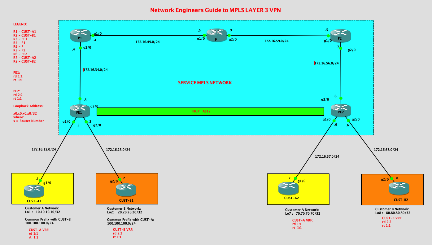
On a high level, I will be building the configurations based on the following steps:
Step 1. Build the MPLS Core . Configure IGP using OSPF and enable LDP. My option is to enable MPLS or the Label Distribution Protocol using “mpls ldp autoconfig” under OSPF process on the MPLS Core network.
Step 2. Assigned and configure the Customer VRF’s. Enabled route distinguisher and route target for each customer. Assigned the VRF’s on the customer link facing the respective CE’s from both PE routers.
Step 3. Configured IBGP between PE1 and PE2. Activate MP-BGP between PE1 and PE2.
Step 4. Configure EBGP between PE’s to the respective CE routers of the customers.
Legend:
R1 – CUST-A1
R2 – CUST-B1
R3 – PE1
R4 – P1
R9 – P
R5 – P2
R6 – PE2
R7 – CUST-A2
R8 – CUST-B2
MPLS – NETWORK
R3 = PE1
|
PE1#show ip int brief
Interface IP-Address OK? Method Status Protocol FastEthernet0/0 unassigned YES unset administratively down down GigabitEthernet1/0 172.16.13.3 YES manual up up GigabitEthernet2/0 172.16.23.3 YES manual up up GigabitEthernet3/0 172.16.34.3 YES manual up up Loopback3 30.30.30.30 YES manual up up router ospf 1 network 30.30.30.30 0.0.0.0
area 0 network 172.16.34.0 0.0.0.255 area 0 interface GigabitEthernet3/0
ip address 172.16.34.3 255.255.255.0 ip ospf priority 0 negotiation auto mpls ip |
R4 = P1
|
P1#show ip int brief
Interface IP-Address OK? Method Status Protocol FastEthernet0/0 unassigned YES unset administratively down down GigabitEthernet1/0 172.16.49.4 YES manual up up GigabitEthernet2/0 172.16.34.4 YES manual up up Loopback4 40.40.40.40 YES manual up up router ospf 1
network 40.40.40.40 0.0.0.0 area 0 network 172.16.34.0 0.0.0.255 area 0 network 172.16.49.0 0.0.0.255 area 0 mpls ldp autoconfig |
R9 = P
|
P#show ip int brief
Interface IP-Address OK? Method Status Protocol FastEthernet0/0 unassigned YES unset administratively down down GigabitEthernet1/0 172.16.49.9 YES manual up up GigabitEthernet2/0 172.16.59.9 YES manual up up Loopback9 90.90.90.90 YES manual up up router ospf 1 network 90.90.90.90 0.0.0.0
area 0 network 172.16.49.0 0.0.0.255 area 0 network 172.16.59.0 0.0.0.255 area 0 mpls ldp autoconfig |
R5 = P2
|
P2#show ip int brief
Interface IP-Address OK? Method Status Protocol FastEthernet0/0 unassigned YES unset administratively down down GigabitEthernet1/0 172.16.59.5 YES manual up up GigabitEthernet2/0 172.16.56.5 YES manual up up Loopback5 50.50.50.50 YES manual up up router ospf 1 network 50.50.50.50 0.0.0.0 area 0
network 172.16.56.0 0.0.0.255 area 0 network 172.16.59.0 0.0.0.255 area 0 mpls ldp autoconfig |
R6 = PE2
|
PE2#show ip int brief
Interface IP-Address OK? Method Status Protocol FastEthernet0/0 unassigned YES unset administratively down down GigabitEthernet1/0 172.16.67.6 YES manual up up GigabitEthernet2/0 172.16.68.6 YES manual up up GigabitEthernet3/0 172.16.56.6 YES manual up up Loopback6 60.60.60.60 YES manual up up interface GigabitEthernet3/0
ip address 172.16.56.6 255.255.255.0 negotiation auto mpls ip router ospf 1 network 60.60.60.60 0.0.0.0 area 0 network 172.16.56.0 0.0.0.255 area 0 |
Customer VRF Configurations:
R3 = PE1
|
ip vrf CUST-A
rd 1:1 route-target export 1:1 route-target import 1:1 ! ip vrf CUST-B rd 2:2 interface GigabitEthernet1/0
ip vrf forwarding CUST-A ip address 172.16.13.3 255.255.255.0 negotiation auto interface GigabitEthernet2/0
ip vrf forwarding CUST-B ip address 172.16.23.3 255.255.255.0 negotiation auto |
R6 = PE2
|
ip vrf CUST-A rd 1:1
route-target export 1:1 route-target import 1:1 ip vrf CUST-B interface GigabitEthernet1/0
ip vrf forwarding CUST-A ip address 172.16.67.6 255.255.255.0 negotiation auto ! interface GigabitEthernet2/0 |
IBGP and MP-BGP Configurations between PE1 and PE2:
R3 = PE1
|
router bgp 12
bgp log-neighbor-changes neighbor 60.60.60.60 remote-as 12 neighbor 60.60.60.60 update-source Loopback3 ! address-family ipv4 no neighbor 60.60.60.60 activate exit-address-family ! address-family vpnv4 neighbor 60.60.60.60 activate neighbor 60.60.60.60 send-community extended exit-address-family ! |
R6 = PE2
|
router bgp 12
bgp log-neighbor-changes neighbor 30.30.30.30 remote-as 12 neighbor 30.30.30.30 update-source Loopback6 ! address-family ipv4 no neighbor 30.30.30.30 activate exit-address-family ! address-family vpnv4 neighbor 30.30.30.30 activate neighbor 30.30.30.30 send-community extended exit-address-family |
EBGP Configurations between PE’s and CE’s:
R1 = CUST-A-HQ
|
router bgp 100
bgp log-neighbor-changes network 10.10.10.10 mask 255.255.255.255 network 100.100.100.0 mask 255.255.255.0 neighbor 172.16.13.3 remote-as 12 |
R7 = CUST-A-BRANCH
|
router bgp 700
bgp log-neighbor-changes network 70.70.70.70 mask 255.255.255.255 neighbor 172.16.67.6 remote-as 12 |
R2 = CUST-B-HQ
|
router bgp 200
bgp log-neighbor-changes network 20.20.20.20 mask 255.255.255.255 network 100.100.100.0 mask 255.255.255.0 neighbor 172.16.23.3 remote-as 12 |
R8 = CUST-B-BRANCH
|
router bgp 800
bgp log-neighbor-changes network 80.80.80.80 mask 255.255.255.255 neighbor 172.16.68.6 remote-as 12 |
Let’s check the eBGP PE router configurations towards the CE’s:
R3 = PE1
|
address-family ipv4 vrf CUST-A
neighbor 172.16.13.1 remote-as 100 neighbor 172.16.13.1 activate exit-address-family ! address-family ipv4 vrf CUST-B neighbor 172.16.23.2 remote-as 200 neighbor 172.16.23.2 activate exit-address-family |
R6 = PE2
|
address-family ipv4 vrf CUST-A
neighbor 172.16.67.7 remote-as 700 neighbor 172.16.67.7 activate exit-address-family ! address-family ipv4 vrf CUST-B neighbor 172.16.68.8 remote-as 800 neighbor 172.16.68.8 activate exit-address-family |
Verification:
Let me check the MPLS CORE routers:
|
OSPF Neighbors
P#show ip ospf neighbor
Neighbor ID Pri State Dead Time Address Interface 50.50.50.50 1 FULL/BDR 00:00:38 172.16.59.5 GigabitEthernet2/0 40.40.40.40 1 FULL/BDR 00:00:37 172.16.49.4 GigabitEthernet1/0 After LDP is enabled:
P#show mpls ldp neighbor
Peer LDP Ident: 40.40.40.40:0; Local LDP Ident 90.90.90.90:0 TCP connection: 40.40.40.40.646 – 90.90.90.90.65164 State: Oper; Msgs sent/rcvd: 309/312; Downstream Up time: 04:20:38 LDP discovery sources: GigabitEthernet1/0, Src IP addr: 172.16.49.4 Addresses bound to peer LDP Ident: 172.16.49.4 172.16.34.4 40.40.40.40 Peer LDP Ident: 50.50.50.50:0; Local LDP Ident 90.90.90.90:0 TCP connection: 50.50.50.50.646 – 90.90.90.90.22167 State: Oper; Msgs sent/rcvd: 310/306; Downstream Up time: 04:19:49 LDP discovery sources: GigabitEthernet2/0, Src IP addr: 172.16.59.5 Addresses bound to peer LDP Ident: 172.16.59.5 172.16.56.5 50.50.50.50 P1#show ip ospf neighbor
Neighbor ID Pri State Dead Time Address Interface P1#show mpls ldp neighbor
Peer LDP Ident: 90.90.90.90:0; Local LDP Ident 40.40.40.40:0 TCP connection: 90.90.90.90.65164 – 40.40.40.40.646 State: Oper; Msgs sent/rcvd: 312/310; Downstream Up time: 04:21:09 LDP discovery sources: GigabitEthernet1/0, Src IP addr: 172.16.49.9 Addresses bound to peer LDP Ident: 172.16.49.9 172.16.59.9 90.90.90.90 Peer LDP Ident: 30.30.30.30:0; Local LDP Ident 40.40.40.40:0 TCP connection: 30.30.30.30.646 – 40.40.40.40.24711 State: Oper; Msgs sent/rcvd: 305/305; Downstream Up time: 04:17:34 LDP discovery sources: GigabitEthernet2/0, Src IP addr: 172.16.34.3 Addresses bound to peer LDP Ident: 172.16.34.3 30.30.30.30 P1# P2#show ip ospf neighbor
Neighbor ID Pri State Dead Time Address Interface P2#show mpls ldp neighbor
Peer LDP Ident: 90.90.90.90:0; Local LDP Ident 50.50.50.50:0 TCP connection: 90.90.90.90.22167 – 50.50.50.50.646 State: Oper; Msgs sent/rcvd: 307/312; Downstream Up time: 04:20:51 LDP discovery sources: GigabitEthernet1/0, Src IP addr: 172.16.59.9 Addresses bound to peer LDP Ident: 172.16.49.9 172.16.59.9 90.90.90.90 Peer LDP Ident: 60.60.60.60:0; Local LDP Ident 50.50.50.50:0 TCP connection: 60.60.60.60.51680 – 50.50.50.50.646 State: Oper; Msgs sent/rcvd: 309/309; Downstream Up time: 04:20:33 LDP discovery sources: GigabitEthernet2/0, Src IP addr: 172.16.56.6 Addresses bound to peer LDP Ident: 172.16.56.6 60.60.60.60 P2# |
|
Note:
|
Now let me verify the iBGP and MP-BGP routes on the PE’s:
|
As observed below, since we enabled MP-BGP for VRF CUST-A, we can see that the the BGP neighbor is established for CE1.
PE1#show bgp vpnv4 unicast vrf CUST-A summary
BGP router identifier 30.30.30.30, local AS number 12 BGP table version is 11, main routing table version 11 3 network entries using 468 bytes of memory 3 path entries using 240 bytes of memory 6/4 BGP path/bestpath attribute entries using 864 bytes of memory 4 BGP AS-PATH entries using 96 bytes of memory 2 BGP extended community entries using 48 bytes of memory 0 BGP route-map cache entries using 0 bytes of memory 0 BGP filter-list cache entries using 0 bytes of memory BGP using 1716 total bytes of memory BGP activity 7/1 prefixes, 7/1 paths, scan interval 60 secs Neighbor V AS MsgRcvd MsgSent TblVer InQ OutQ Up/Down State/PfxRcd 172.16.13.1 4 100 424 422 11 0 0 06:19:54 2 PE1# PE1#show bgp vpnv4 unicast vrf CUST-B summary BGP router identifier 30.30.30.30, local AS number 12 BGP table version is 11, main routing table version 11 3 network entries using 468 bytes of memory 3 path entries using 240 bytes of memory 6/4 BGP path/bestpath attribute entries using 864 bytes of memory 4 BGP AS-PATH entries using 96 bytes of memory 2 BGP extended community entries using 48 bytes of memory 0 BGP route-map cache entries using 0 bytes of memory 0 BGP filter-list cache entries using 0 bytes of memory BGP using 1716 total bytes of memory BGP activity 7/1 prefixes, 7/1 paths, scan interval 60 secs Neighbor V AS MsgRcvd MsgSent TblVer InQ OutQ Up/Down State/PfxRcd 172.16.23.2 4 200 389 390 11 0 0 05:48:43 2 Checking the prefixes advertised on each customer VRF’s:
PE1#show bgp vpnv4 unicast all
BGP table version is 11, local router ID is 30.30.30.30 Status codes: s suppressed, d damped, h history, * valid, > best, i – internal, r RIB-failure, S Stale, m multipath, b backup-path, f RT-Filter, x best-external, a additional-path, c RIB-compressed, Origin codes: i – IGP, e – EGP, ? – incomplete RPKI validation codes: V valid, I invalid, N Not found Network Next Hop Metric LocPrf Weight Path Route Distinguisher: 1:1 (default for vrf CUST-A) *> 10.10.10.10/32 172.16.13.1 0 0 100 i *>i 70.70.70.70/32 60.60.60.60 0 100 0 700 i *> 100.100.100.0/24 172.16.13.1 0 0 100 i Route Distinguisher: 2:2 (default for vrf CUST-B) *> 20.20.20.20/32 172.16.23.2 0 0 200 i *>i 80.80.80.80/32 60.60.60.60 0 100 0 800 i *> 100.100.100.0/24 172.16.23.2 0 0 200 i PE1# Checking on PE2,
PE2#show bgp vpnv4 unicast vrf CUST-A summary
BGP router identifier 60.60.60.60, local AS number 12 BGP table version is 14, main routing table version 14 3 network entries using 468 bytes of memory 3 path entries using 240 bytes of memory 6/4 BGP path/bestpath attribute entries using 864 bytes of memory 4 BGP AS-PATH entries using 96 bytes of memory 2 BGP extended community entries using 48 bytes of memory 0 BGP route-map cache entries using 0 bytes of memory 0 BGP filter-list cache entries using 0 bytes of memory BGP using 1716 total bytes of memory BGP activity 7/1 prefixes, 7/1 paths, scan interval 60 secs Neighbor V AS MsgRcvd MsgSent TblVer InQ OutQ Up/Down State/PfxRcd 172.16.67.7 4 700 371 373 14 0 0 05:33:41 1 PE2#show bgp vpnv4 unicast vrf CUST-B summary BGP router identifier 60.60.60.60, local AS number 12 BGP table version is 14, main routing table version 14 3 network entries using 468 bytes of memory 3 path entries using 240 bytes of memory 6/4 BGP path/bestpath attribute entries using 864 bytes of memory 4 BGP AS-PATH entries using 96 bytes of memory 2 BGP extended community entries using 48 bytes of memory 0 BGP route-map cache entries using 0 bytes of memory 0 BGP filter-list cache entries using 0 bytes of memory BGP using 1716 total bytes of memory BGP activity 7/1 prefixes, 7/1 paths, scan interval 60 secs Neighbor V AS MsgRcvd MsgSent TblVer InQ OutQ Up/Down State/PfxRcd 172.16.68.8 4 800 389 393 14 0 0 05:50:50 1 PE2# PE2#show bgp vpnv4 unicast all BGP table version is 14, local router ID is 60.60.60.60 Status codes: s suppressed, d damped, h history, * valid, > best, i – internal, r RIB-failure, S Stale, m multipath, b backup-path, f RT-Filter, x best-external, a additional-path, c RIB-compressed, Origin codes: i – IGP, e – EGP, ? – incomplete RPKI validation codes: V valid, I invalid, N Not found Network Next Hop Metric LocPrf Weight Path Route Distinguisher: 1:1 (default for vrf CUST-A) *>i 10.10.10.10/32 30.30.30.30 0 100 0 100 i *> 70.70.70.70/32 172.16.67.7 0 0 700 i *>i 100.100.100.0/24 30.30.30.30 0 100 0 100 i Route Distinguisher: 2:2 (default for vrf CUST-B) *>i 20.20.20.20/32 30.30.30.30 0 100 0 200 i *> 80.80.80.80/32 172.16.68.8 0 0 800 i *>i 100.100.100.0/24 30.30.30.30 0 100 0 200 i PE2# As we can see above, all the Prefixes that were advertised by the CE’s are all on the PE’s routing table.
Now let’s check the CE routing table. I would expect on CE1 ( CUST-A1) to have the 70.70.70.70/32 network as that is being advertised by CUST-A2.
CUST-A1#show ip route bgp
Codes: L – local, C – connected, S – static, R – RIP, M – mobile, B – BGP D – EIGRP, EX – EIGRP external, O – OSPF, IA – OSPF inter area N1 – OSPF NSSA external type 1, N2 – OSPF NSSA external type 2 E1 – OSPF external type 1, E2 – OSPF external type 2 i – IS-IS, su – IS-IS summary, L1 – IS-IS level-1, L2 – IS-IS level-2 ia – IS-IS inter area, * – candidate default, U – per-user static route o – ODR, P – periodic downloaded static route, H – NHRP, l – LISP + – replicated route, % – next hop override Gateway of last resort is not set 70.0.0.0/32 is subnetted, 1 subnets B 70.70.70.70 [20/0] via 172.16.13.3, 05:34:39 CUST-A1# Similarly, CUST-A2 is also receiving the prefix advertised by CUST-A1.
CUST-A2#show ip route bgp
Codes: L – local, C – connected, S – static, R – RIP, M – mobile, B – BGP D – EIGRP, EX – EIGRP external, O – OSPF, IA – OSPF inter area N1 – OSPF NSSA external type 1, N2 – OSPF NSSA external type 2 E1 – OSPF external type 1, E2 – OSPF external type 2 i – IS-IS, su – IS-IS summary, L1 – IS-IS level-1, L2 – IS-IS level-2 ia – IS-IS inter area, * – candidate default, U – per-user static route o – ODR, P – periodic downloaded static route, H – NHRP, l – LISP + – replicated route, % – next hop override Gateway of last resort is not set 10.0.0.0/32 is subnetted, 1 subnets B 10.10.10.10 [20/0] via 172.16.67.6, 05:35:00 100.0.0.0/24 is subnetted, 1 subnets B 100.100.100.0 [20/0] via 172.16.67.6, 05:32:57 CUST-A2# This should be the same prefix that is being advertised by PE2:
PE2#show bgp vpnv4 unicast vrf CUST-A neighbors 172.16.67.7 advertised-routes
BGP table version is 14, local router ID is 60.60.60.60 Status codes: s suppressed, d damped, h history, * valid, > best, i – internal, r RIB-failure, S Stale, m multipath, b backup-path, f RT-Filter, x best-external, a additional-path, c RIB-compressed, Origin codes: i – IGP, e – EGP, ? – incomplete RPKI validation codes: V valid, I invalid, N Not found Network Next Hop Metric LocPrf Weight Path Route Distinguisher: 1:1 (default for vrf CUST-A) *>i 10.10.10.10/32 30.30.30.30 0 100 0 100 i *>i 100.100.100.0/24 30.30.30.30 0 100 0 100 i Total number of prefixes 2 PE2# Lets check CUST-B:
PE2#show bgp vpnv4 unicast vrf CUST-B neighbors 172.16.68.8 advertised-routes
BGP table version is 14, local router ID is 60.60.60.60 Status codes: s suppressed, d damped, h history, * valid, > best, i – internal, r RIB-failure, S Stale, m multipath, b backup-path, f RT-Filter, x best-external, a additional-path, c RIB-compressed, Origin codes: i – IGP, e – EGP, ? – incomplete RPKI validation codes: V valid, I invalid, N Not found Network Next Hop Metric LocPrf Weight Path Route Distinguisher: 2:2 (default for vrf CUST-B) *>i 20.20.20.20/32 30.30.30.30 0 100 0 200 i *>i 100.100.100.0/24 30.30.30.30 0 100 0 200 i Total number of prefixes 2 PE2# CUST-B2#show ip route bgp
Codes: L – local, C – connected, S – static, R – RIP, M – mobile, B – BGP D – EIGRP, EX – EIGRP external, O – OSPF, IA – OSPF inter area N1 – OSPF NSSA external type 1, N2 – OSPF NSSA external type 2 E1 – OSPF external type 1, E2 – OSPF external type 2 i – IS-IS, su – IS-IS summary, L1 – IS-IS level-1, L2 – IS-IS level-2 ia – IS-IS inter area, * – candidate default, U – per-user static route o – ODR, P – periodic downloaded static route, H – NHRP, l – LISP + – replicated route, % – next hop override Gateway of last resort is not set 20.0.0.0/32 is subnetted, 1 subnets B 20.20.20.20 [20/0] via 172.16.68.6, 05:51:10 100.0.0.0/24 is subnetted, 1 subnets B 100.100.100.0 [20/0] via 172.16.68.6, 05:31:19 CUST-B2# By this time, let’s try to check the connectivity:
CUST-A-HQ to CUST-A-Branch:
CUST-A1#ping 70.70.70.70 source 10.10.10.10
Type escape sequence to abort. Sending 5, 100-byte ICMP Echos to 70.70.70.70, timeout is 2 seconds: Packet sent with a source address of 10.10.10.10 !!!!! Success rate is 100 percent (5/5), round-trip min/avg/max = 68/83/108 ms CUST-A1# CUST-A1# CUST-A1#traceroute 70.70.70.70 source 10.10.10.10 Type escape sequence to abort. Tracing the route to 70.70.70.70 VRF info: (vrf in name/id, vrf out name/id) 1 172.16.13.3 28 msec 8 msec 8 msec 2 172.16.34.4 [MPLS: Labels 18/17 Exp 0] 48 msec 68 msec 68 msec 3 172.16.49.9 [MPLS: Labels 19/17 Exp 0] 104 msec 104 msec 84 msec 4 172.16.59.5 [MPLS: Labels 18/17 Exp 0] 48 msec 100 msec 76 msec 5 172.16.67.6 [MPLS: Label 17 Exp 0] 56 msec 64 msec 56 msec 6 172.16.67.7 88 msec 104 msec 80 msec CUST-A1# CUST-B-HQ to CUST-B-BRANCH:
CUST-B1#ping 80.80.80.80 source 20.20.20.20
Type escape sequence to abort. Sending 5, 100-byte ICMP Echos to 80.80.80.80, timeout is 2 seconds: Packet sent with a source address of 20.20.20.20 !!!!! Success rate is 100 percent (5/5), round-trip min/avg/max = 48/100/152 ms CUST-B1# CUST-B1# CUST-B1# CUST-B1#traceroute 80.80.80.80 source 20.20.20.20 Type escape sequence to abort. Tracing the route to 80.80.80.80 VRF info: (vrf in name/id, vrf out name/id) 1 172.16.23.3 12 msec 20 msec 8 msec 2 172.16.34.4 [MPLS: Labels 18/16 Exp 0] 80 msec 52 msec 64 msec 3 172.16.49.9 [MPLS: Labels 19/16 Exp 0] 100 msec 76 msec 92 msec 4 172.16.59.5 [MPLS: Labels 18/16 Exp 0] 92 msec 52 msec 68 msec 5 172.16.68.6 [MPLS: Label 16 Exp 0] 104 msec 60 msec 72 msec 6 172.16.68.8 112 msec 88 msec 100 msec CUST-B1# Some important notes:
PE1#show bgp vpnv4 unicast vrf CUST-A neighbors 172.16.13.1 advertised-routes
There are more to discussed about MPLS Layer 3 VPN’s but I think this post provide some of the basic informations to configure MPLS Layer 3 VPN.
##########################END##########################################
|
p, li { white-space: pre-wrap; }
Network Engineers Guide to IS-IS – Part 2
This is the second part of my IS-IS routing protocol post. I’m adding Level-2 router on my IS-IS routing domain to explore further on how IS-IS protocol works.
|
Some key pointers to take note on the difference of the routes received by a Level-1 router and Level-2 router:
|

|
Considerations:
AFI is set to 49
System ID will be 0000.0000.000X where X is the router number.
Legend:
R1 – Level 1 router
R2 – Level 1-2 router
R3 – Level 1-2 router
R4 – Level 1 router
R5 – Level 2 router
|
|
R1:
interface Loopback1 R1# LSP Database |
|
Tips:
|
|
R1#show ip route isis
Codes: L – local, C – connected, S – static, R – RIP, M – mobile, B – BGP |
|
Tips:
|
|
Let’s have a look on R2 configurations:
interface Loopback2 |
|
IS-IS neighbors:
R2#show isis neighbors R2# R2#show isis database verbose |
|
Few things to note on the routing table on R2:
R2#show ip route isis
Codes: L – local, C – connected, S – static, R – RIP, M – mobile, B – BGP D – EIGRP, EX – EIGRP external, O – OSPF, IA – OSPF inter area N1 – OSPF NSSA external type 1, N2 – OSPF NSSA external type 2 E1 – OSPF external type 1, E2 – OSPF external type 2 i – IS-IS, su – IS-IS summary, L1 – IS-IS level-1, L2 – IS-IS level-2 ia – IS-IS inter area, * – candidate default, U – per-user static route o – ODR, P – periodic downloaded static route, H – NHRP, l – LISP + – replicated route, % – next hop override Gateway of last resort is not set 10.0.0.0/32 is subnetted, 1 subnets i L1 10.10.10.10 [115/20] via 172.16.12.1, 01:39:01, GigabitEthernet2/0 40.0.0.0/32 is subnetted, 1 subnets i L2 40.40.40.40 [115/30] via 172.16.23.3, 01:00:56, GigabitEthernet1/0 50.0.0.0/32 is subnetted, 1 subnets i L2 50.50.50.50 [115/30] via 172.16.23.3, 01:00:47, GigabitEthernet1/0 172.16.0.0/16 is variably subnetted, 6 subnets, 2 masks i L2 172.16.34.0/24 [115/20] via 172.16.23.3, 01:00:56, GigabitEthernet1/0 i L2 172.16.35.0/24 [115/20] via 172.16.23.3, 01:00:56, GigabitEthernet1/0 R2# |
Looking at R3, 3 neighbors were formed :
|
|
R3 Configurations:
interface Loopback3
ip address 30.30.30.30 255.255.255.255
interface GigabitEthernet1/0
ip address 172.16.23.3 255.255.255.0
ip router isis
negotiation auto
!
interface GigabitEthernet2/0
ip address 172.16.34.3 255.255.255.0
ip router isis
negotiation auto
!
interface GigabitEthernet3/0
ip address 172.16.35.3 255.255.255.0
ip router isis
negotiation auto
!
router isis
net 49.0034.0000.0000.0003.00
net 49.0035.0000.0000.0003.00
R3#show isis neighbors R3# R3#show ip route isis
Codes: L – local, C – connected, S – static, R – RIP, M – mobile, B – BGP
D – EIGRP, EX – EIGRP external, O – OSPF, IA – OSPF inter area
N1 – OSPF NSSA external type 1, N2 – OSPF NSSA external type 2
E1 – OSPF external type 1, E2 – OSPF external type 2
i – IS-IS, su – IS-IS summary, L1 – IS-IS level-1, L2 – IS-IS level-2
ia – IS-IS inter area, * – candidate default, U – per-user static route
o – ODR, P – periodic downloaded static route, H – NHRP, l – LISP
+ – replicated route, % – next hop override
Gateway of last resort is not set
10.0.0.0/32 is subnetted, 1 subnets
i L2 10.10.10.10 [115/30] via 172.16.23.2, 01:55:31, GigabitEthernet1/0
20.0.0.0/32 is subnetted, 1 subnets
i L2 20.20.20.20 [115/20] via 172.16.23.2, 01:55:31, GigabitEthernet1/0
40.0.0.0/32 is subnetted, 1 subnets
i L1 40.40.40.40 [115/20] via 172.16.34.4, 02:05:14, GigabitEthernet2/0
50.0.0.0/32 is subnetted, 1 subnets
i L2 50.50.50.50 [115/20] via 172.16.35.5, 01:57:53, GigabitEthernet3/0
172.16.0.0/16 is variably subnetted, 7 subnets, 2 masks
i L2 172.16.12.0/24 [115/20] via 172.16.23.2, 01:55:31, GigabitEthernet1/0
R3#
|
|
R3 will have the prefix with all its connected interface that are advertised into IS-IS and the prefix it learned from both the Level-1 routers and Level-2 routers.
|
|
R4:
interface Loopback4
ip address 40.40.40.40 255.255.255.255 ip router isis ! interface GigabitEthernet1/0 no ip address shutdown negotiation auto ! interface GigabitEthernet2/0 ip address 172.16.34.4 255.255.255.0 ip router isis negotiation auto ! router isis net 49.0034.0000.0000.0004.00 is-type level-1 |
|
IS-IS Neighbors:
R4#show isis neighbors
System Id Type Interface IP Address State Holdtime Circuit Id
R3 L1 Gi2/0 172.16.34.3 UP 23 R4.01
R4#
|
| LSP Database: R4#show isis database verbose IS-IS Level-1 Link State Database: LSPID LSP Seq Num LSP Checksum LSP Holdtime ATT/P/OL R3.00-00 0x00000010 0x8111 688 1/0/0 Area Address: 49.0034 Area Address: 49.0035 NLPID: 0xCC Hostname: R3 IP Address: 172.16.35.3 Metric: 10 IP 172.16.34.0 255.255.255.0 Metric: 10 IP 172.16.35.0 255.255.255.0 Metric: 10 IP 172.16.23.0 255.255.255.0 Metric: 10 IS R4.01 R4.00-00 * 0x0000000E 0xF11D 394 0/0/0 Area Address: 49.0034 NLPID: 0xCC Hostname: R4 IP Address: 40.40.40.40 Metric: 10 IP 40.40.40.40 255.255.255.255 Metric: 10 IP 172.16.34.0 255.255.255.0 Metric: 10 IS R4.01 R4.01-00 * 0x0000000B 0xA69C 955 0/0/0 Metric: 0 IS R4.00 Metric: 0 IS R3.00 R4# |
:
R4#show ip route isis Codes: L – local, C – connected, S – static, R – RIP, M – mobile, B – BGP D – EIGRP, EX – EIGRP external, O – OSPF, IA – OSPF inter area N1 – OSPF NSSA external type 1, N2 – OSPF NSSA external type 2 E1 – OSPF external type 1, E2 – OSPF external type 2 i – IS-IS, su – IS-IS summary, L1 – IS-IS level-1, L2 – IS-IS level-2 ia – IS-IS inter area, * – candidate default, U – per-user static route o – ODR, P – periodic downloaded static route, H – NHRP, l – LISP + – replicated route, % – next hop override Gateway of last resort is 172.16.34.3 to network 0.0.0.0 i*L1 0.0.0.0/0 [115/10] via 172.16.34.3, 02:05:12, GigabitEthernet2/0 |
|
As observed R4 also have injected a default route. Since R4 is a Level-1 router, it will only learned prefixes advertise on Area 34 and a default route.
|
|
R5:
interface Loopback5
ip address 50.50.50.50 255.255.255.255
ip router isis
interface GigabitEthernet3/0
ip address 172.16.35.5 255.255.255.0
ip router isis
negotiation auto
!
router isis
net 49.0035.0000.0000.0005.00
is-type level-2-only
|
|
R5#show isis database verbose
|
|
Routes/Prefixes received by R5.
R5#show ip route isis
Codes: L – local, C – connected, S – static, R – RIP, M – mobile, B – BGP
D – EIGRP, EX – EIGRP external, O – OSPF, IA – OSPF inter area
N1 – OSPF NSSA external type 1, N2 – OSPF NSSA external type 2
E1 – OSPF external type 1, E2 – OSPF external type 2
i – IS-IS, su – IS-IS summary, L1 – IS-IS level-1, L2 – IS-IS level-2
ia – IS-IS inter area, * – candidate default, U – per-user static route
o – ODR, P – periodic downloaded static route, H – NHRP, l – LISP
+ – replicated route, % – next hop override
Gateway of last resort is not set
10.0.0.0/32 is subnetted, 1 subnets
i L2 10.10.10.10 [115/40] via 172.16.35.3, 03:34:45, GigabitEthernet3/0
20.0.0.0/32 is subnetted, 1 subnets
i L2 20.20.20.20 [115/30] via 172.16.35.3, 03:34:45, GigabitEthernet3/0
40.0.0.0/32 is subnetted, 1 subnets
i L2 40.40.40.40 [115/30] via 172.16.35.3, 03:37:07, GigabitEthernet3/0
172.16.0.0/16 is variably subnetted, 5 subnets, 2 masks
i L2 172.16.12.0/24 [115/30] via 172.16.35.3, 03:34:45, GigabitEthernet3/0
i L2 172.16.23.0/24 [115/20] via 172.16.35.3, 03:34:45, GigabitEthernet3/0
i L2 172.16.34.0/24 [115/20] via 172.16.35.3, 03:37:07, GigabitEthernet3/0
R5#
|
|
Tips:
Level-2 routers will only received Level-2 LSP’s. In case of R5, it only has the L2 prefixes from other areas.
|
Let’s check the connectivity between the routers:
|
From R4 towards R1 ( Level-1 router in Area 34 to another Level-1 router in Area 12):
R4#ping 10.10.10.10 source 40.40.40.40
Type escape sequence to abort.
Sending 5, 100-byte ICMP Echos to 10.10.10.10, timeout is 2 seconds:
Packet sent with a source address of 40.40.40.40
!!!!!
Success rate is 100 percent (5/5), round-trip min/avg/max = 24/40/60 ms
R4#traceroute 10.10.10.10 source 40.40.40.40
Type escape sequence to abort.
Tracing the route to 10.10.10.10
VRF info: (vrf in name/id, vrf out name/id)
1 172.16.34.3 40 msec 28 msec 12 msec
2 172.16.23.2 12 msec 32 msec 28 msec
3 172.16.12.1 56 msec 44 msec 12 msec
R4#
From R1 ( Level-1 router) in Area 12 to R5 ( Level-2 router) in Area 35.
R1#ping 50.50.50.50 source 10.10.10.10
Type escape sequence to abort.
Sending 5, 100-byte ICMP Echos to 50.50.50.50, timeout is 2 seconds:
Packet sent with a source address of 10.10.10.10
!!!!!
Success rate is 100 percent (5/5), round-trip min/avg/max = 12/34/68 ms
R1#traceroute 50.50.50.50 source 10.10.10.10
Type escape sequence to abort.
Tracing the route to 50.50.50.50
VRF info: (vrf in name/id, vrf out name/id)
1 172.16.12.2 4 msec 20 msec 24 msec
2 172.16.23.3 12 msec 24 msec 32 msec
3 172.16.35.5 76 msec 48 msec 44 msec
R1#
|
###################################END#########################################
Network Engineers Guide to IS-IS Configurations
On this post, I will be exploring how to configured IS-IS routing protocol and provide some basic concepts on how IS-IS routing protocol works.
I will be using the below topology to illustrate the basic concept and configurations of IS-IS.

Legend:
R1 & R4 – Level-1 routers
R2 & R3 – Level 1-2 routers
So the question is what is IS-IS routing protocol? It was originally developed by DEC for Connectionless-Mode Network Service. It’s one of the two Link-State routing protocol ( aside from OSPF). There are couple of differences between the two, e.g. there is no backbone 0 for IS-IS and this provides flexibility of deployment ( no more virtual-link).
But before moving to the configurations part, we need to understand some concepts about IS-IS.
There are 3 types of IS-IS routers:
- Level 1 System– This is an intra-area router . It can only formed neighbor adjacency with another L1 router.
- Level 2 System – This is a backbone router. It knows about the prefix on intra-area and inter-area.
- Level 1-2 System – By the name itself, it can act as Level 1 or Level 2 router. This router usually is considered the backbone connecting two different areas as it could function as L1 or L2 system router.
There is no backbone 0 for IS-IS unlike OSPF. Backbone could be in any area number but the backbone router could either be a Level 1-2 or Level 2 system.
If you still remember LSA’s for OSPF, the equivalent of this for IS-IS is LSP or Link State Packet. So Link State Packet contained the following information’s when they are exchange with the neighboring router:
- Prefixes
- Neighbor
- Metric
Each IS-IS router must have a unique identifier called Network Entity Title ( NET) . NET have two major parts called IDP or Initial Domain Part consisting of Authority and Format Identifier (AFI) and Initial Domain Identifier (IDI). AN AFI of 49 signifies a private networks and usually the IDI represents the IS-IS area. The second part of NET is the DSO or the Domain Specific Part which consist of High Order DSP, System ID and NSEL. (Reference RFC 1195 – https://tools.ietf.org/html/rfc1195)
Considerations for this laboratory:
- AFI is set to 49
- System ID will be 0000.0000.000X where X is the router number.
I will go through the configurations part and will explore the LSP Level 1 and Level 2 database on all the routers.
R1 Configurations:
R1#show ip int brief
Interface IP-Address OK? Method Status Protocol
FastEthernet0/0 unassigned YES unset administratively down down
GigabitEthernet1/0 172.16.12.1 YES manual up up
GigabitEthernet2/0 unassigned YES unset administratively down down
Loopback1 11.11.11.11 YES manual up up
router isis
net 49.0012.0000.0000.0001.00
is-type level-1
log-adjacency-changes
interface GigabitEthernet1/0
ip address 172.16.12.1 255.255.255.0
ip router isis
negotiation auto
interface Loopback1
ip address 11.11.11.11 255.255.255.255
ip router isis
R2 Configurations:
R2#show ip interface brief
Interface IP-Address OK? Method Status Protocol
FastEthernet0/0 unassigned YES unset administratively down down
GigabitEthernet1/0 172.16.12.2 YES manual up up
GigabitEthernet2/0 172.16.23.2 YES manual up up
Loopback0 unassigned YES unset up up
Loopback2 22.22.22.22 YES manual up up
router isis
net 49.0012.0000.0000.0002.00
log-adjacency-changes
interface Loopback2
ip address 22.22.22.22 255.255.255.255
ip router isis
interface GigabitEthernet1/0
ip address 172.16.12.2 255.255.255.0
ip router isis
negotiation auto
!
interface GigabitEthernet2/0
ip address 172.16.23.2 255.255.255.0
ip router isis
negotiation auto
Note: I have configured R2 as Level 1-2 system router but the configurations is not showing this details as seen above. By default a Cisco router is a Level 1-2 system.
R2(config)#router isis
R2(config-router)#is-type level-1-2
R3 Configurations:
R3#show ip int brief
Interface IP-Address OK? Method Status Protocol
FastEthernet0/0 unassigned YES unset administratively down down
GigabitEthernet1/0 172.16.34.3 YES manual up up
GigabitEthernet2/0 172.16.23.3 YES manual up up
Loopback3 33.33.33.33 YES manual up up
R3#
interface Loopback3
ip address 33.33.33.33 255.255.255.255
ip router isis
interface GigabitEthernet1/0
ip address 172.16.34.3 255.255.255.0
ip router isis
negotiation auto
!
interface GigabitEthernet2/0
ip address 172.16.23.3 255.255.255.0
ip router isis
negotiation auto
!
router isis
net 49.0034.0000.0000.0003.00
log-adjacency-changes
Similarly above, R3 is also a Level 1-2 system and its a default IS-IS configs for Cisco device.
R4 Configurations:
R4#show ip int brief
Interface IP-Address OK? Method Status Protocol
FastEthernet0/0 unassigned YES unset administratively down down
GigabitEthernet1/0 172.16.34.4 YES manual up up
GigabitEthernet2/0 unassigned YES unset administratively down down
Loopback0 unassigned YES unset up up
Loopback4 44.44.44.44 YES manual up up
R4#
interface Loopback4
ip address 44.44.44.44 255.255.255.255
ip router isis
!
interface GigabitEthernet1/0
ip address 172.16.34.4 255.255.255.0
ip router isis
negotiation auto
!
router isis
net 49.0034.0000.0000.0004.00
is-type level-1
Let’s check the IS-IS neighbor. IS-IS neighbor is established between R1 and R2.
R1#show isis neighbors
System Id Type Interface IP Address State Holdtime Circuit Id
R2 L1 Gi1/0 172.16.12.2 UP 6 R2.01
R1#
Let’s check the R1 Link State Packet L1 database. As seen below, R1 have received LSP for the prefix which I highlighted in red from R2.
R1#show isis database verbose
IS-IS Level-1 Link State Database:
LSPID LSP Seq Num LSP Checksum LSP Holdtime ATT/P/OL
R1.00-00 * 0x00000010 0x3402 873 0/0/0
Area Address: 49.0012
NLPID: 0xCC
Hostname: R1
IP Address: 11.11.11.11
Metric: 10 IP 172.16.12.0 255.255.255.0
Metric: 10 IP 11.11.11.11 255.255.255.255
Metric: 10 IS R2.01
R2.00-00 0x0000000E 0xE97E 545 1/0/0
Area Address: 49.0012
NLPID: 0xCC
Hostname: R2
IP Address: 22.22.22.22
Metric: 10 IP 172.16.12.0 255.255.255.0
Metric: 10 IP 22.22.22.22 255.255.255.255
Metric: 10 IP 172.16.23.0 255.255.255.0
Metric: 10 IS R2.01
R2.01-00 0x00000009 0x6CDE 1063 0/0/0
Metric: 0 IS R2.00
Metric: 0 IS R1.00
R1#
Let’s check the IS-IS routes on R1.
- A default route is created on R1. This is one rule created for IS-IS in which a prefix from other Level 1 router on a different area will not be advertise on another Level 1 system from a different area. In order to established connectivity a default route will be introduced
- IS-IS Administrative distance is 115 with link metrics of 10. A metric of 10 is constant irregardless of the link bandwidth.
- The prefix 22.22.22.22/32 from R2 is learned via IS-IS with Admin Distance of 115 but since its two hops away from R1 , the metrics is 20.
- It also learned the prefix ( 172.16.23.0/24) used between the Level 1-2 routers ( R2 & R3) with a admin distance of 115 and metric of 20.
R1#show ip route isis
Codes: L – local, C – connected, S – static, R – RIP, M – mobile, B – BGP
D – EIGRP, EX – EIGRP external, O – OSPF, IA – OSPF inter area
N1 – OSPF NSSA external type 1, N2 – OSPF NSSA external type 2
E1 – OSPF external type 1, E2 – OSPF external type 2
i – IS-IS, su – IS-IS summary, L1 – IS-IS level-1, L2 – IS-IS level-2
ia – IS-IS inter area, * – candidate default, U – per-user static route
o – ODR, P – periodic downloaded static route, H – NHRP, l – LISP
+ – replicated route, % – next hop override
Gateway of last resort is 172.16.12.2 to network 0.0.0.0
i*L1 0.0.0.0/0 [115/10] via 172.16.12.2, 00:38:12, GigabitEthernet1/0
22.0.0.0/32 is subnetted, 1 subnets
i L1 22.22.22.22 [115/20] via 172.16.12.2, 01:44:10, GigabitEthernet1/0
172.16.0.0/16 is variably subnetted, 3 subnets, 2 masks
i L1 172.16.23.0/24 [115/20] via 172.16.12.2, 00:39:19, GigabitEthernet1/0
R1#
By this time, lets check R2,
R2#show isis neighbors
System Id Type Interface IP Address State Holdtime Circuit Id
R1 L1 Gi1/0 172.16.12.1 UP 25 R2.01
R3 L2 Gi2/0 172.16.23.3 UP 8 R3.01
R2#
Note:
- There are two LSP database created on R2, one is for Level-1 Link State Database and the other 1 is for Level-2 Link State Database.
- The rules is that all directly connected interfaces that are configured for IS-IS are added to both Level-1 LSP’s and Level-2 LSP’s.
- Also Level 1-2 routers will add a prefixes it learned from Level 1 LSP’s to their Level 2 LSP’s.
- Level 1 LSP’s are only flooded within an area while Level 2 LSP’s are flooded within the backbone.
- One more thing as we have observed on R1, it generates a default routes towards Level 1-2 routers when it sees the attached bit. The attached bit is set by the Level 1-2 router on the Level 1 LSP update. We have to take note that Level 1 LSP’s are not allowed between backbone but the Level 1 LSP’s is copied to Level 2 LSP’s with an altered bit to indicate that its a prefix coming from Level 1 router. This attached bit prefix is advertised to the other backbone router in other area which eventually been sync with the LSP database on the Level 1 router of that area. It created a default route when he sees this attached bit to ensure reachability with the other Level-1 router.
R2 has the following Link State Packet database:
R2#show isis database verbose
IS-IS Level-1 Link State Database:
LSPID LSP Seq Num LSP Checksum LSP Holdtime ATT/P/OL
R1.00-00 0x00000011 0x3203 1166 0/0/0
Area Address: 49.0012
NLPID: 0xCC
Hostname: R1
IP Address: 11.11.11.11
Metric: 10 IP 172.16.12.0 255.255.255.0
Metric: 10 IP 11.11.11.11 255.255.255.255
Metric: 10 IS R2.01
R2.00-00 * 0x0000000F 0xE77F 780 1/0/0
Area Address: 49.0012
NLPID: 0xCC
Hostname: R2
IP Address: 22.22.22.22
Metric: 10 IP 172.16.12.0 255.255.255.0
Metric: 10 IP 22.22.22.22 255.255.255.255
Metric: 10 IP 172.16.23.0 255.255.255.0
Metric: 10 IS R2.01
R2.01-00 * 0x00000009 0x6CDE 532 0/0/0
Metric: 0 IS R2.00
Metric: 0 IS R1.00
IS-IS Level-2 Link State Database:
LSPID LSP Seq Num LSP Checksum LSP Holdtime ATT/P/OL
R2.00-00 * 0x00000005 0x2A80 562 0/0/0
Area Address: 49.0012
NLPID: 0xCC
Hostname: R2
IP Address: 22.22.22.22
Metric: 10 IS R3.01
Metric: 20 IP 11.11.11.11 255.255.255.255
Metric: 10 IP 22.22.22.22 255.255.255.255
Metric: 10 IP 172.16.12.0 255.255.255.0
Metric: 10 IP 172.16.23.0 255.255.255.0
R3.00-00 0x0000000A 0x840A 1001 0/0/0
Area Address: 49.0034
NLPID: 0xCC
Hostname: R3
IP Address: 33.33.33.33
Metric: 10 IS R3.01
Metric: 10 IP 33.33.33.33 255.255.255.255
Metric: 20 IP 44.44.44.44 255.255.255.255
Metric: 10 IP 172.16.23.0 255.255.255.0
Metric: 10 IP 172.16.34.0 255.255.255.0
R3.01-00 0x00000004 0x27AC 944 0/0/0
Metric: 0 IS R3.00
Metric: 0 IS R2.00
R2#
R2#show ip route isis
Codes: L – local, C – connected, S – static, R – RIP, M – mobile, B – BGP
D – EIGRP, EX – EIGRP external, O – OSPF, IA – OSPF inter area
N1 – OSPF NSSA external type 1, N2 – OSPF NSSA external type 2
E1 – OSPF external type 1, E2 – OSPF external type 2
i – IS-IS, su – IS-IS summary, L1 – IS-IS level-1, L2 – IS-IS level-2
ia – IS-IS inter area, * – candidate default, U – per-user static route
o – ODR, P – periodic downloaded static route, H – NHRP, l – LISP
+ – replicated route, % – next hop override
Gateway of last resort is not set
11.0.0.0/32 is subnetted, 1 subnets
i L1 11.11.11.11 [115/20] via 172.16.12.1, 02:15:02, GigabitEthernet1/0
33.0.0.0/32 is subnetted, 1 subnets
i L2 33.33.33.33 [115/20] via 172.16.23.3, 01:02:35, GigabitEthernet2/0
44.0.0.0/32 is subnetted, 1 subnets
i L2 44.44.44.44 [115/30] via 172.16.23.3, 00:57:43, GigabitEthernet2/0
172.16.0.0/16 is variably subnetted, 5 subnets, 2 masks
i L2 172.16.34.0/24 [115/20] via 172.16.23.3, 00:57:49, GigabitEthernet2/0
R2#
Let’s check R3 as well,
R3#show isis neighbors
System Id Type Interface IP Address State Holdtime Circuit Id
R2 L2 Gi2/0 172.16.23.2 UP 25 R3.01
R4 L1 Gi1/0 172.16.34.4 UP 9 R4.01
R3#
R3#show isis database verbose
IS-IS Level-1 Link State Database:
LSPID LSP Seq Num LSP Checksum LSP Holdtime ATT/P/OL
R3.00-00 * 0x0000000B 0x2BAB 1005 1/0/0
Area Address: 49.0034
NLPID: 0xCC
Hostname: R3
IP Address: 33.33.33.33
Metric: 10 IP 172.16.23.0 255.255.255.0
Metric: 10 IP 33.33.33.33 255.255.255.255
Metric: 10 IP 172.16.34.0 255.255.255.0
Metric: 10 IS R4.01
R4.00-00 0x00000009 0xC42F 875 0/0/0
Area Address: 49.0034
NLPID: 0xCC
Hostname: R4
IP Address: 44.44.44.44
Metric: 10 IP 172.16.34.0 255.255.255.0
Metric: 10 IP 44.44.44.44 255.255.255.255
Metric: 10 IS R4.01
R4.01-00 0x00000005 0xB296 907 0/0/0
Metric: 0 IS R4.00
Metric: 0 IS R3.00
IS-IS Level-2 Link State Database:
LSPID LSP Seq Num LSP Checksum LSP Holdtime ATT/P/OL
R2.00-00 0x00000007 0x2682 1169 0/0/0
Area Address: 49.0012
NLPID: 0xCC
Hostname: R2
IP Address: 22.22.22.22
Metric: 10 IS R3.01
Metric: 20 IP 11.11.11.11 255.255.255.255
Metric: 10 IP 22.22.22.22 255.255.255.255
Metric: 10 IP 172.16.12.0 255.255.255.0
Metric: 10 IP 172.16.23.0 255.255.255.0
R3.00-00 * 0x0000000B 0x820B 846 0/0/0
Area Address: 49.0034
NLPID: 0xCC
Hostname: R3
IP Address: 33.33.33.33
Metric: 10 IS R3.01
Metric: 10 IP 33.33.33.33 255.255.255.255
Metric: 20 IP 44.44.44.44 255.255.255.255
Metric: 10 IP 172.16.23.0 255.255.255.0
Metric: 10 IP 172.16.34.0 255.255.255.0
R3.01-00 * 0x00000005 0x25AD 660 0/0/0
Metric: 0 IS R3.00
Metric: 0 IS R2.00
R3#
R3#show ip route isis
Codes: L – local, C – connected, S – static, R – RIP, M – mobile, B – BGP
D – EIGRP, EX – EIGRP external, O – OSPF, IA – OSPF inter area
N1 – OSPF NSSA external type 1, N2 – OSPF NSSA external type 2
E1 – OSPF external type 1, E2 – OSPF external type 2
i – IS-IS, su – IS-IS summary, L1 – IS-IS level-1, L2 – IS-IS level-2
ia – IS-IS inter area, * – candidate default, U – per-user static route
o – ODR, P – periodic downloaded static route, H – NHRP, l – LISP
+ – replicated route, % – next hop override
Gateway of last resort is not set
11.0.0.0/32 is subnetted, 1 subnets
i L2 11.11.11.11 [115/30] via 172.16.23.2, 01:03:25, GigabitEthernet2/0
22.0.0.0/32 is subnetted, 1 subnets
i L2 22.22.22.22 [115/20] via 172.16.23.2, 01:03:25, GigabitEthernet2/0
44.0.0.0/32 is subnetted, 1 subnets
i L1 44.44.44.44 [115/20] via 172.16.34.4, 00:58:37, GigabitEthernet1/0
172.16.0.0/16 is variably subnetted, 5 subnets, 2 masks
i L2 172.16.12.0/24 [115/20] via 172.16.23.2, 01:03:25, GigabitEthernet2/0
R3#
And finally R4. As observed R4 has the default route in order to reach the Prefix advertise into IS-IS from R1.
R4#show isis neighbors
System Id Type Interface IP Address State Holdtime Circuit Id
R3 L1 Gi1/0 172.16.34.3 UP 25 R4.01
R4#show isis database verbose
IS-IS Level-1 Link State Database:
LSPID LSP Seq Num LSP Checksum LSP Holdtime ATT/P/OL
R3.00-00 0x0000000B 0x2BAB 931 1/0/0
Area Address: 49.0034
NLPID: 0xCC
Hostname: R3
IP Address: 33.33.33.33
Metric: 10 IP 172.16.23.0 255.255.255.0
Metric: 10 IP 33.33.33.33 255.255.255.255
Metric: 10 IP 172.16.34.0 255.255.255.0
Metric: 10 IS R4.01
R4.00-00 * 0x00000009 0xC42F 808 0/0/0
Area Address: 49.0034
NLPID: 0xCC
Hostname: R4
IP Address: 44.44.44.44
Metric: 10 IP 172.16.34.0 255.255.255.0
Metric: 10 IP 44.44.44.44 255.255.255.255
Metric: 10 IS R4.01
R4.01-00 * 0x00000005 0xB296 840 0/0/0
Metric: 0 IS R4.00
Metric: 0 IS R3.00
R4#
R4#show ip route isis
Codes: L – local, C – connected, S – static, R – RIP, M – mobile, B – BGP
D – EIGRP, EX – EIGRP external, O – OSPF, IA – OSPF inter area
N1 – OSPF NSSA external type 1, N2 – OSPF NSSA external type 2
E1 – OSPF external type 1, E2 – OSPF external type 2
i – IS-IS, su – IS-IS summary, L1 – IS-IS level-1, L2 – IS-IS level-2
ia – IS-IS inter area, * – candidate default, U – per-user static route
o – ODR, P – periodic downloaded static route, H – NHRP, l – LISP
+ – replicated route, % – next hop override
Gateway of last resort is 172.16.34.3 to network 0.0.0.0
i*L1 0.0.0.0/0 [115/10] via 172.16.34.3, 00:58:52, GigabitEthernet1/0
33.0.0.0/32 is subnetted, 1 subnets
i L1 33.33.33.33 [115/20] via 172.16.34.3, 00:58:52, GigabitEthernet1/0
172.16.0.0/16 is variably subnetted, 3 subnets, 2 masks
i L1 172.16.23.0/24 [115/20] via 172.16.34.3, 00:58:52, GigabitEthernet1/0
R4#
Let’s check the connectivity:
R4#ping 11.11.11.11 source 44.44.44.44
Type escape sequence to abort.
Sending 5, 100-byte ICMP Echos to 11.11.11.11, timeout is 2 seconds:
Packet sent with a source address of 44.44.44.44
!!!!!
Success rate is 100 percent (5/5), round-trip min/avg/max = 60/83/112 ms
R4#traceroute 11.11.11.11 source 44.44.44.44
Type escape sequence to abort.
Tracing the route to 11.11.11.11
VRF info: (vrf in name/id, vrf out name/id)
1 172.16.34.3 60 msec 32 msec 56 msec
2 172.16.23.2 80 msec 80 msec 60 msec
3 172.16.12.1 60 msec 60 msec 80 msec
##########################END#######################################
DMVPN Explained
On this post, I’m going to explore the basics of DMVPN and will show how to configure Phase 1 DMVPN. So the first question we need to ask is what is DMVPN and what it is used for. DMVPM is basically a hub and spoke tunneling technology. In fact, it is one form of a VPN that allows spoke to communicate with other spoke sites without going through the Hub.
To understand DMVPN, there are other important protocols to learned such as GRE, dynamic routing protocol such as OSPF and BGP and Next Hop Redundancy Protocol. DMVPN is not secured as their is no encryption involved but we could run IPSec on top of DMVPN to encrypted our data.
On this particular post, I’m gonna explain DMVPN in action and I will go through the details on each configuration steps.
But before moving forward, as mentioned, we need to understand how GRE works. I have a good explanation on configuring GRE Tunnel on this post. GRE tunnel could be built between two distant sites via the WAN or Internet links. We could build GRE over the internet and adding IPSEC to encrypt data or we could also built a GRE Tunnels via an MPLS link. The thing to note here is GRE Tunnel is built between two peers (two devices). But with DMVPN, multipoint-GRE will be introduced.
This means that our hub could built a separate GRE tunnels to two different spokes. In my lab, I will be showing some good examples with multipoint-GRE Tunnels which I built on the hub.
Next thing thing to understand is “Next Hop Redundancy Protocol (NHRP)”. So what is the purpose of NHRP. I’m gonna answer this with some scenario. Example we have a HUB router that is connected to two different spokes. The Hub router will be able to communicate directly with the two spokes as it was able to build the GRE tunnels. But what about if the two spokes want to reach each other. This will not be possible as we only built the GRE Tunnels between the Hub and the Spokes.
So NHRP is our hero. Some concepts to understand here:
- We need to have a NHRP Server which is usually the Hub
- The Spokes will be considered as NHRP Client.
- The NHRP clients will need to informed the NHRP server of their public IP address or the NBMA address. This could be done using NHRP registration request.
- The NHRP server will build a mapping between the Tunnel IP address of the spokes against the NBMA address.
- The NHRP resolution request will happen if the spokes desires to reach each other. The NHRP resolution request will be sent out by NHRP client to NHRP server and asking for the NBMA address of the other spoke router.
- The NHRP resolution reply will be send out by the NHRP server towards the spokes providing the NBMA address of the other spoke routers.
In short, what NHRP does is it maps the Tunnel IP address to the NMBA address of the spokes.
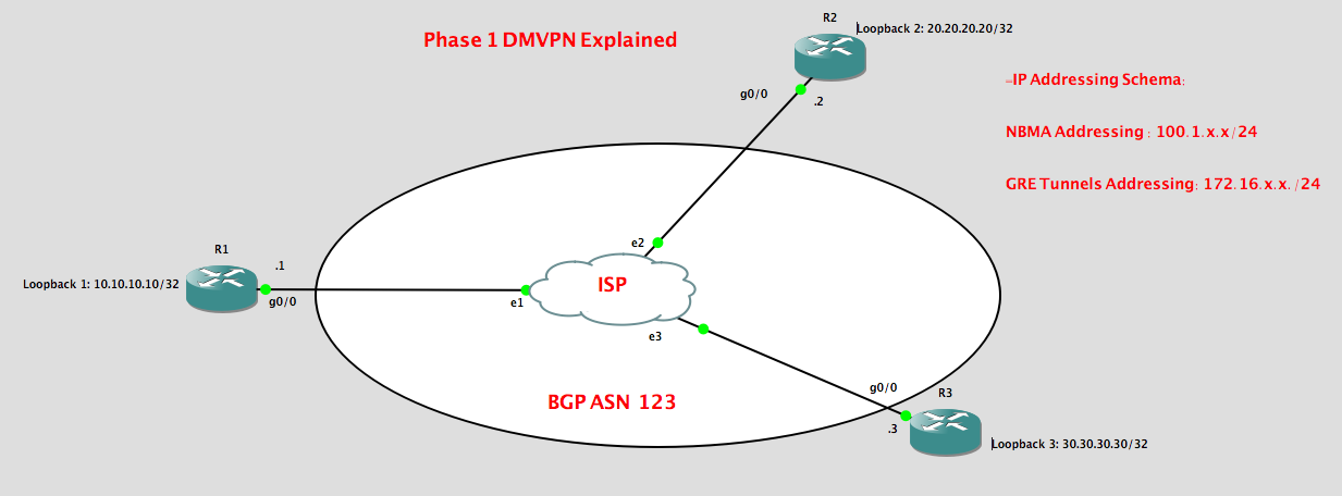
Below configurations will established my layer 2 connectivity
Thats a quick summary of DMVPN but I would go to the exciting part which is the configurations.
On my lab, I will focus on configuring Phase 1 DMVPN. So what is Phase 1 DMVPN? My answer to this is simple, all traffic between Spokes have to go through the Hub. The Hub router will be responsible for routing the traffic towards the spoke. Mainly, this type of DMVPN is used just to have a control of traffic between Spokes. No direct GRE tunnel is built between spokes.
So here’s my lab topology:
Based on my topology, I have the basic details as follows:
- I’m running BGP on my ISP to established the connection between Hub and Spoke. This simulate an actual environment where main HQ and Branch offices are connected through the internet. The ISP are connecting to the HQ and Spokes via BGP.
- BGP have to be established between the HUb and spokes in order to build the GRE Tunnels.
Key task for this lab:
1. Configure layer 2 trunking to used a single interface using dot1q encapsulation between Hub and Spokes. This will established the layer 2 connectivity which formed the underlay network.
2. To established layer 3 connectivity on the underlay network, configure iBGP.
3. Build the GRE tunnels between the Hub and Spokes. This will be the starting point of building the overlay network.
4. Enable OSPF between the Hub and Spokes and advertise the loopback on each router.
5. Verify the connectivity.
Legends:
R1 = Hub , R2 = Spoke 1, R3 = Spoke 2
Below configurations will established my layer 2 connectivity
R1 configurations:
interface GigabitEthernet0/0
no ip address
duplex full
speed 1000
media-type gbic
negotiation auto
!
R1 –> R2
interface GigabitEthernet0/0.12
encapsulation dot1Q 12
ip address 100.1.12.1 255.255.255.0
R1 –> R3
interface GigabitEthernet0/0.13
encapsulation dot1Q 13
ip address 100.1.13.1 255.255.255.0
R2 configurations:
interface GigabitEthernet0/0
no ip address
duplex full
speed 1000
media-type gbic
negotiation auto
!
R2 –> R1
interface GigabitEthernet0/0.12
encapsulation dot1Q 12
ip address 100.1.12.2 255.255.255.0
!
R3 configurations:
interface GigabitEthernet0/0
no ip address
duplex full
speed 1000
media-type gbic
negotiation auto
!
R3 –> R1
interface GigabitEthernet0/0.13
encapsulation dot1Q 13
ip address 100.1.13.3 255.255.255.0
Now let’s check whether the physical link are up on the three routers:
R1#show ip int brief
Interface IP-Address OK? Method Status Protocol
Ethernet0/0 unassigned YES NVRAM administratively down down
GigabitEthernet0/0 unassigned YES NVRAM up up
GigabitEthernet0/0.12 100.1.12.1 YES NVRAM up up
GigabitEthernet0/0.13 100.1.13.1 YES NVRAM up up
R2#show ip int brief
Interface IP-Address OK? Method Status Protocol
Ethernet0/0 unassigned YES NVRAM administratively down down
GigabitEthernet0/0 unassigned YES NVRAM up up
GigabitEthernet0/0.12 100.1.12.2 YES NVRAM up up
R3#show ip interface brief
Interface IP-Address OK? Method Status Protocol
Ethernet0/0 unassigned YES NVRAM administratively down down
GigabitEthernet0/0 unassigned YES NVRAM up up
GigabitEthernet0/0.13 100.1.13.3 YES NVRAM up up
Now lets’ enable iBGP between R1 towards R2 and R1 towards R3:
R1:
router bgp 123
no synchronization
bgp log-neighbor-changes
neighbor 100.1.12.2 remote-as 123
neighbor 100.1.13.3 remote-as 123
no auto-summary
R2:
router bgp 123
no synchronization
bgp log-neighbor-changes
neighbor 100.1.12.1 remote-as 123
no auto-summary
R3:
router bgp 123
no synchronization
bgp log-neighbor-changes
neighbor 100.1.13.1 remote-as 123
no auto-summary
Now lets verify the BGP sessions:
R1#show ip bgp summary
BGP router identifier 172.16.13.1, local AS number 123
BGP table version is 1, main routing table version 1
Neighbor V AS MsgRcvd MsgSent TblVer InQ OutQ Up/Down State/PfxRcd
100.1.12.2 4 123 113 115 1 0 0 01:41:49 0
100.1.13.3 4 123 114 114 1 0 0 01:41:47 0
R1#
R2#show ip bgp summary
BGP router identifier 172.16.12.2, local AS number 123
BGP table version is 1, main routing table version 1
Neighbor V AS MsgRcvd MsgSent TblVer InQ OutQ Up/Down State/PfxRcd
100.1.12.1 4 123 115 114 1 0 0 01:42:01 0
R2#
R3#show ip bgp summary
BGP router identifier 172.16.13.3, local AS number 123
BGP table version is 1, main routing table version 1
Neighbor V AS MsgRcvd MsgSent TblVer InQ OutQ Up/Down State/PfxRcd
100.1.13.1 4 123 115 114 1 0 0 01:42:04 0
R3#
🔺So as seen above L3 connectivity is working with all the established BGP sessions.
Next is build the GRE Tunnels.
R1:
interface Tunnel0
ip address 172.16.12.1 255.255.255.0
no ip redirects
ip nhrp authentication CISCO
ip nhrp map multicast dynamic
ip nhrp network-id 1
tunnel source GigabitEthernet0/0.12
tunnel mode gre multipoint
!
!
interface Tunnel1
ip address 172.16.13.1 255.255.255.0
no ip redirects
ip nhrp authentication CISCO
ip nhrp map multicast dynamic
ip nhrp network-id 2
tunnel source GigabitEthernet0/0.13
tunnel mode gre multipoint
So let me go through the details above:
1. Tunnel IP address is assigned for each tunnel between R1 and R2 and R1 and R3.
2. NHRP authentication is enabled
3. NHRP mapping is configured as multicast dynamic. Dynamic is used in Hub as it does not know the IP address of the spokes and with the NHRP registration request when the tunnel is build, it will automatically add the IP addresses to the multicast destination list when the spokes register themselves.
4. NHRP network-id is used to distinguished the GRE Tunnels if there are one or more tunnels to build.
5. We have set the tunnel source with the sub-interface GigabitEthernet0/0.13 and
GigabitEthernet0/0.12
6. We have changed the gre mode into multipoint as by default GRE is point-to-point.
e.g.
R1(config-if)#tunnel mode gre ?
ip over IP
ipv6 over IPv6
multipoint over IP (multipoint)
R2:
interface Tunnel0
ip address 172.16.12.2 255.255.255.0
ip nhrp authentication CISCO
ip nhrp map multicast 100.1.12.1
ip nhrp map 172.16.12.1 100.1.12.1
ip nhrp network-id 1
ip nhrp nhs 172.16.12.1
tunnel source GigabitEthernet0/0.12
tunnel destination 100.1.12.1
R3:
interface Tunnel0
ip address 172.16.13.3 255.255.255.0
ip nhrp authentication CISCO
ip nhrp map 172.16.13.1 100.1.13.1
ip nhrp map multicast 100.1.13.1
ip nhrp network-id 2
ip nhrp nhs 172.16.13.1
tunnel source GigabitEthernet0/0.13
tunnel destination 100.1.13.1
As seen above, what was change on the spoke configuration are as follows:
1. NHRP mapping is configured statically ( Tunnel IP address is map to the NBMA address)
2. NHRP multicast ismap with the NHRP server Tunnel IP address.
3. Network ID is configured based on the network id assigned by the Hub router.
4. NHRP Next Hop Server ( NHS) is assigned statically with the Tunnel IP address of the Hub router.
Now lets verify if the spokes are registered with the Hub:
R1#show dmvpn
Legend: Attrb –> S – Static, D – Dynamic, I – Incomplete
N – NATed, L – Local, X – No Socket
# Ent –> Number of NHRP entries with same NBMA peer
NHS Status: E –> Expecting Replies, R –> Responding
UpDn Time –> Up or Down Time for a Tunnel
==========================================================================
Interface: Tunnel0, IPv4 NHRP Details
Type:Hub, NHRP Peers:1,
# Ent Peer NBMA Addr Peer Tunnel Add State UpDn Tm Attrb
—– ————— ————— —– ——– —–
1 100.1.12.2 172.16.12.2 UP 02:04:29 D
Interface: Tunnel1, IPv4 NHRP Details
Type:Hub, NHRP Peers:1,
# Ent Peer NBMA Addr Peer Tunnel Add State UpDn Tm Attrb
—– ————— ————— —– ——– —–
1 100.1.13.3 172.16.13.3 UP 02:04:26 D
R2#show dmvpn
Legend: Attrb –> S – Static, D – Dynamic, I – Incomplete
N – NATed, L – Local, X – No Socket
# Ent –> Number of NHRP entries with same NBMA peer
NHS Status: E –> Expecting Replies, R –> Responding
UpDn Time –> Up or Down Time for a Tunnel
==========================================================================
Interface: Tunnel0, IPv4 NHRP Details
Type:Spoke, NHRP Peers:1,
# Ent Peer NBMA Addr Peer Tunnel Add State UpDn Tm Attrb
—– ————— ————— —– ——– —–
1 100.1.12.1 172.16.12.1 UP 02:01:42 S
R3#show dmvpn
Legend: Attrb –> S – Static, D – Dynamic, I – Incomplete
N – NATed, L – Local, X – No Socket
# Ent –> Number of NHRP entries with same NBMA peer
NHS Status: E –> Expecting Replies, R –> Responding
UpDn Time –> Up or Down Time for a Tunnel
==========================================================================
Interface: Tunnel0, IPv4 NHRP Details
Type:Spoke, NHRP Peers:1,
# Ent Peer NBMA Addr Peer Tunnel Add State UpDn Tm Attrb
—– ————— ————— —– ——– —–
1 100.1.13.1 172.16.13.1 UP 02:04:28 S
So the mapping of the NBMA address with the Peer Tunnel IP address is available on the Hub as well as on the spokes.
A detailed look as well using “show ip nhrp” ppovide the NBMA address.
R3#show ip nhrp
172.16.13.1/32 via 172.16.13.1
Tunnel0 created 02:08:30, never expire
Type: static, Flags:
NBMA address: 100.1.13.1
Now we need to enable OSPF between the HUB and spokes and advertise the Loopback:
R1:
router ospf 1
log-adjacency-changes
network 10.10.10.10 0.0.0.0 area 0
network 172.16.12.0 0.0.0.255 area 0
network 172.16.13.0 0.0.0.255 area 0
R2:
router ospf 1
log-adjacency-changes
network 20.20.20.20 0.0.0.0 area 0
network 172.16.12.0 0.0.0.255 area 0
R3:
router ospf 1
log-adjacency-changes
network 30.30.30.30 0.0.0.0 area 0
network 172.16.13.0 0.0.0.255 area 0
By default OSPF network types is POINT_TO_POINT. Let’s change this to Broadcast .
R1#show ip ospf interface tunnel 0
Tunnel0 is up, line protocol is up
Internet Address 172.16.12.1/24, Area 0
Process ID 1, Router ID 172.16.13.1, Network Type POINT_TO_POINT, Cost: 1000
Topology-MTID Cost Disabled Shutdown Topology Name
0 1000 no no Base
Transmit Delay is 1 sec, State POINT_TO_POINT
Timer intervals configured, Hello 10, Dead 40, Wait 40, Retransmit 5
oob-resync timeout 40
Hello due in 00:00:08
Supports Link-local Signaling (LLS)
Cisco NSF helper support enabled
IETF NSF helper support enabled
Index 1/1, flood queue length 0
Next 0x0(0)/0x0(0)
Last flood scan length is 1, maximum is 2
Last flood scan time is 4 msec, maximum is 4 msec
Neighbor Count is 1, Adjacent neighbor count is 1
Adjacent with neighbor 172.16.12.2
Suppress hello for 0 neighbor(s)
!
R1#show run int tunnel 0
Building configuration…
Current configuration : 258 bytes
!
interface Tunnel0
ip address 172.16.12.1 255.255.255.0
no ip redirects
ip nhrp authentication CISCO
ip nhrp map multicast dynamic
ip nhrp network-id 1
ip ospf network broadcast
tunnel source GigabitEthernet0/0.12
tunnel mode gre multipoint
R2#show run int tunnel 0
Building configuration…
Current configuration : 328 bytes
!
interface Tunnel0
ip address 172.16.12.2 255.255.255.0
ip nhrp authentication CISCO
ip nhrp map multicast 100.1.12.1
ip nhrp map 172.16.12.1 100.1.12.1
ip nhrp network-id 1
ip nhrp nhs 172.16.12.1
ip ospf network broadcast
ip ospf priority 0
tunnel source GigabitEthernet0/0.12
tunnel destination 100.1.12.1
R3#show run int tunnel 0
Building configuration…
Current configuration : 328 bytes
!
interface Tunnel0
ip address 172.16.13.3 255.255.255.0
ip nhrp authentication CISCO
ip nhrp map 172.16.13.1 100.1.13.1
ip nhrp map multicast 100.1.13.1
ip nhrp network-id 2
ip nhrp nhs 172.16.13.1
ip ospf network broadcast
ip ospf priority 0
tunnel source GigabitEthernet0/0.13
tunnel destination 100.1.13.1
I also need to ensure that R2 and R3 will not be participating in DR/BDR elections. I will set R1 as the DR and R2 and R3 as DROTHER by setting the OSPF Priority. An OSPF Priority of “0” means the router is not participating in the DR and BDR election and will be set as DROTHER.
Enter configuration commands, one per line. End with CNTL/Z.
R1(config)#int tunnel 0
R1(config-if)#ip ospf priority ?
Priority
R1(config-if)#ip ospf priority 100
R1(config-if)#int tun1
R1(config-if)#ip ospf priority 100
R1(config-if)#
Let verify this with the “show ip ospf interface ” command.
R1#show ip ospf interface tunnel 0
Tunnel0 is up, line protocol is up
Internet Address 172.16.12.1/24, Area 0
Process ID 1, Router ID 172.16.13.1, Network Type BROADCAST, Cost: 1000
Topology-MTID Cost Disabled Shutdown Topology Name
0 1000 no no Base
Transmit Delay is 1 sec, State DR, Priority 100
Designated Router (ID) 172.16.13.1, Interface address 172.16.12.1
No backup designated router on this network
Timer intervals configured, Hello 10, Dead 40, Wait 40, Retransmit 5
oob-resync timeout 40
Hello due in 00:00:08
Supports Link-local Signaling (LLS)
Cisco NSF helper support enabled
IETF NSF helper support enabled
Index 1/1, flood queue length 0
Next 0x0(0)/0x0(0)
Last flood scan length is 2, maximum is 2
Last flood scan time is 0 msec, maximum is 4 msec
Neighbor Count is 1, Adjacent neighbor count is 1
Adjacent with neighbor 172.16.12.2
Suppress hello for 0 neighbor(s)
R1#show ip ospf interface tunnel 1
Tunnel1 is up, line protocol is up
Internet Address 172.16.13.1/24, Area 0
Process ID 1, Router ID 172.16.13.1, Network Type BROADCAST, Cost: 1000
Topology-MTID Cost Disabled Shutdown Topology Name
0 1000 no no Base
Transmit Delay is 1 sec, State DR, Priority 100
Designated Router (ID) 172.16.13.1, Interface address 172.16.13.1
No backup designated router on this network
Timer intervals configured, Hello 10, Dead 40, Wait 40, Retransmit 5
oob-resync timeout 40
Hello due in 00:00:00
Supports Link-local Signaling (LLS)
Cisco NSF helper support enabled
IETF NSF helper support enabled
Index 2/2, flood queue length 0
Next 0x0(0)/0x0(0)
Last flood scan length is 2, maximum is 2
Last flood scan time is 0 msec, maximum is 0 msec
Neighbor Count is 1, Adjacent neighbor count is 1
Adjacent with neighbor 172.16.13.3
Suppress hello for 0 neighbor(s)
R2#show ip ospf interface tunnel 0
Tunnel0 is up, line protocol is up
Internet Address 172.16.12.2/24, Area 0
Process ID 1, Router ID 172.16.12.2, Network Type BROADCAST, Cost: 1000
Topology-MTID Cost Disabled Shutdown Topology Name
0 1000 no no Base
Transmit Delay is 1 sec, State DROTHER, Priority 0
Designated Router (ID) 172.16.13.1, Interface address 172.16.12.1
No backup designated router on this network
Timer intervals configured, Hello 10, Dead 40, Wait 40, Retransmit 5
oob-resync timeout 40
Hello due in 00:00:01
Supports Link-local Signaling (LLS)
Cisco NSF helper support enabled
IETF NSF helper support enabled
Index 1/1, flood queue length 0
Next 0x0(0)/0x0(0)
Last flood scan length is 1, maximum is 1
Last flood scan time is 0 msec, maximum is 0 msec
Neighbor Count is 1, Adjacent neighbor count is 1
Adjacent with neighbor 172.16.13.1 (Designated Router)
Suppress hello for 0 neighbor(s)
R3#show ip ospf interface tunnel 0
Tunnel0 is up, line protocol is up
Internet Address 172.16.13.3/24, Area 0
Process ID 1, Router ID 172.16.13.3, Network Type BROADCAST, Cost: 1000
Topology-MTID Cost Disabled Shutdown Topology Name
0 1000 no no Base
Transmit Delay is 1 sec, State DROTHER, Priority 0
Designated Router (ID) 172.16.13.1, Interface address 172.16.13.1
No backup designated router on this network
Timer intervals configured, Hello 10, Dead 40, Wait 40, Retransmit 5
oob-resync timeout 40
Hello due in 00:00:01
Supports Link-local Signaling (LLS)
Cisco NSF helper support enabled
IETF NSF helper support enabled
Index 1/1, flood queue length 0
Next 0x0(0)/0x0(0)
Last flood scan length is 1, maximum is 2
Last flood scan time is 4 msec, maximum is 4 msec
Neighbor Count is 1, Adjacent neighbor count is 1
Adjacent with neighbor 172.16.13.1 (Designated Router)
Suppress hello for 0 neighbor(s)
We can check the status from here,
R1#show ip ospf neighbor
Neighbor ID Pri State Dead Time Address Interface
172.16.13.3 0 FULL/DROTHER 00:00:35 172.16.13.3 Tunnel1
172.16.12.2 0 FULL/DROTHER 00:00:38 172.16.12.2 Tunnel0
R1#
R2#show ip ospf neighbor
Neighbor ID Pri State Dead Time Address Interface
172.16.13.1 100 FULL/DR 00:00:39 172.16.12.1 Tunnel0
R2#
R3#show ip ospf neighbor
Neighbor ID Pri State Dead Time Address Interface
172.16.13.1 100 FULL/DR 00:00:33 172.16.13.1 Tunnel0
R3#
Now, lets check the routes :
R1#show ip route ospf
Codes: L – local, C – connected, S – static, R – RIP, M – mobile, B – BGP
D – EIGRP, EX – EIGRP external, O – OSPF, IA – OSPF inter area
N1 – OSPF NSSA external type 1, N2 – OSPF NSSA external type 2
E1 – OSPF external type 1, E2 – OSPF external type 2
i – IS-IS, su – IS-IS summary, L1 – IS-IS level-1, L2 – IS-IS level-2
ia – IS-IS inter area, * – candidate default, U – per-user static route
o – ODR, P – periodic downloaded static route, + – replicated route
Gateway of last resort is not set
20.0.0.0/32 is subnetted, 1 subnets
O 20.20.20.20 [110/1001] via 172.16.12.2, 00:14:06, Tunnel0
30.0.0.0/32 is subnetted, 1 subnets
O 30.30.30.30 [110/1001] via 172.16.13.3, 00:14:16, Tunnel1
R1#
R2#show ip route ospf
Codes: L – local, C – connected, S – static, R – RIP, M – mobile, B – BGP
D – EIGRP, EX – EIGRP external, O – OSPF, IA – OSPF inter area
N1 – OSPF NSSA external type 1, N2 – OSPF NSSA external type 2
E1 – OSPF external type 1, E2 – OSPF external type 2
i – IS-IS, su – IS-IS summary, L1 – IS-IS level-1, L2 – IS-IS level-2
ia – IS-IS inter area, * – candidate default, U – per-user static route
o – ODR, P – periodic downloaded static route, + – replicated route
Gateway of last resort is not set
10.0.0.0/32 is subnetted, 1 subnets
O 10.10.10.10 [110/1001] via 172.16.12.1, 00:14:27, Tunnel0
30.0.0.0/32 is subnetted, 1 subnets
O 30.30.30.30 [110/2001] via 172.16.12.1, 00:14:27, Tunnel0
172.16.0.0/16 is variably subnetted, 3 subnets, 2 masks
O 172.16.13.0/24 [110/2000] via 172.16.12.1, 00:14:27, Tunnel0
R2#
R3#show ip route ospf
Codes: L – local, C – connected, S – static, R – RIP, M – mobile, B – BGP
D – EIGRP, EX – EIGRP external, O – OSPF, IA – OSPF inter area
N1 – OSPF NSSA external type 1, N2 – OSPF NSSA external type 2
E1 – OSPF external type 1, E2 – OSPF external type 2
i – IS-IS, su – IS-IS summary, L1 – IS-IS level-1, L2 – IS-IS level-2
ia – IS-IS inter area, * – candidate default, U – per-user static route
o – ODR, P – periodic downloaded static route, + – replicated route
Gateway of last resort is not set
10.0.0.0/32 is subnetted, 1 subnets
O 10.10.10.10 [110/1001] via 172.16.13.1, 00:13:59, Tunnel0
20.0.0.0/32 is subnetted, 1 subnets
O 20.20.20.20 [110/2001] via 172.16.13.1, 00:13:49, Tunnel0
172.16.0.0/16 is variably subnetted, 3 subnets, 2 masks
O 172.16.12.0/24 [110/2000] via 172.16.13.1, 00:13:59, Tunnel0
R3#
And Finally lets verify dataplane connectivity,
R1#ping 20.20.20.20 source 10.10.10.10
Type escape sequence to abort.
Sending 5, 100-byte ICMP Echos to 20.20.20.20, timeout is 2 seconds:
Packet sent with a source address of 10.10.10.10
!!!!!
Success rate is 100 percent (5/5), round-trip min/avg/max = 8/11/16 ms
*May 5 01:32:43.643: NHRP: NHRP successfully resolved 172.16.12.2 to NBMA 100.1.12.2
*May 5 01:32:43.651: NHRP: NHRP successfully resolved 172.16.12.2 to NBMA 100.1.12.2
*May 5 01:32:43.667: NHRP: NHRP successfully resolved 172.16.12.2 to NBMA 100.1.12.2
*May 5 01:32:43.675: NHRP: NHRP successfully resolved 172.16.12.2 to NBMA 100.1.12.2
*May 5 01:32:43.687: NHRP: NHRP successfully resolved 172.16.12.2 to NBMA 100.1.12.2
R1#ping 30.30.30.30 source 10.10.10.10
Type escape sequence to abort.
Sending 5, 100-byte ICMP Echos to 30.30.30.30, timeout is 2 seconds:
Packet sent with a source address of 10.10.10.10
!!!!!
Success rate is 100 percent (5/5), round-trip min/avg/max = 12/14/20 ms
R1#
*May 5 01:32:55.151: NHRP: NHRP successfully resolved 172.16.13.3 to NBMA 100.1.13.3
*May 5 01:32:55.163: NHRP: NHRP successfully resolved 172.16.13.3 to NBMA 100.1.13.3
*May 5 01:32:55.187: NHRP: NHRP successfully resolved 172.16.13.3 to NBMA 100.1.13.3
*May 5 01:32:55.203: NHRP: NHRP successfully resolved 172.16.13.3 to NBMA 100.1.13.3
*May 5 01:32:55.215: NHRP: NHRP successfully resolved 172.16.13.3 to NBMA 100.1.13.3
R1#
R1#traceroute 30.30.30.30 source 10.10.10.10
Type escape sequence to abort.
Tracing the route to 30.30.30.30
1 172.16.13.3 20 msec 20 msec 16 msec
R1#
Just to elaborate a bit about the various stages of NHRP , I have tried to run a debug on R1 and shutdown the links on R2 (spoke1).
R1#debug nhrp
NHRP protocol debugging is on
R1#
*May 5 01:36:30.575: NHRP: Receive Registration Request via Tunnel0 vrf 0, packet size: 105
*May 5 01:36:30.579: NHRP: netid_in = 1, to_us = 1
*May 5 01:36:30.579: NHRP: Adding Tunnel Endpoints (VPN: 172.16.12.2, NBMA: 100.1.12.2)
*May 5 01:36:30.583: NHRP: Cache already has a subblock node attached for
Tunnel Endpoints (VPN: 172.16.12.2, NBMA: 100.1.12.2)
*May 5 01:36:30.583: NHRP: Tu0: Found and skipping dynamic multicast mapping NBMA: 100.1.12.2
*May 5 01:36:30.587: NHRP: Added dynamic multicast mapping for
NBMA: 100.1.12.2
*May 5 01:36:30.587: NHRP: New mandatory length: 32
*May 5 01:36:30.587: NHRP:
R1#Attempting to send packet via DEST 172.16.12.2
*May 5 01:36:30.591: NHRP: NHRP successfully resolved 172.16.12.2 to NBMA 100.1.12.2
*May 5 01:36:30.591: NHRP: Encapsulation succeeded. Tunnel IP addr 100.1.12.2
*May 5 01:36:30.591: NHRP: Send Registration Reply via Tunnel0 vrf 0, packet size: 125
*May 5 01:36:30.591: NHRP: 149 bytes out Tunnel0
*May 5 01:36:31.379: NHRP: Receive Registration Request via Tunnel0 vrf 0, packet size: 105
*May 5 01:36:31.379: NHRP: netid_in = 1, to_us = 1
*May 5 01:36:31.383: NHRP: Adding Tunnel Endpoints (VPN: 172.16.12.2, NBMA: 100.1.12.2)
*May 5 01:36:31.383: NHRP: Cache already has a subblock node attached for
Tunnel Endpoints (VPN: 172.16.12.2, NBMA: 100.1.12.2)
*May 5 01:36:31.387: NHRP: Tu0: Found and skipping dynamic multicast mapping NBMA: 100.1.12.2
*May 5 01:36:31.387: NHRP: Added dynamic multicast mapping for
NBMA: 100.1.12.2
*May 5 01:36:31.387: NHRP: New mand
R1#atory length: 32
*May 5 01:36:31.387: NHRP: Attempting to send packet via DEST 172.16.12.2
*May 5 01:36:31.387: NHRP: NHRP successfully resolved 172.16.12.2 to NBMA 100.1.12.2
*May 5 01:36:31.387: NHRP: Encapsulation succeeded. Tunnel IP addr 100.1.12.2
*May 5 01:36:31.387: NHRP: Send Registration Reply via Tunnel0 vrf 0, packet size: 125
*May 5 01:36:31.387: NHRP: 149 bytes out Tunnel0
*May 5 01:36:31.651: NHRP: Receive Registration Request via Tunnel0 vrf 0, packet size: 105
*May 5 01:36:31.651: NHRP: netid_in = 1, to_us = 1
*May 5 01:36:31.655: NHRP: Adding Tunnel Endpoints (VPN: 172.16.12.2, NBMA: 100.1.12.2)
*May 5 01:36:31.655: NHRP: Cache already has a subblock node attached for
Tunnel Endpoints (VPN: 172.16.12.2, NBMA: 100.1.12.2)
*May 5 01:36:31.659: NHRP: Tu0: Found and skipping dynamic multicast mapping NBMA: 100.1.12.2
*May 5 01:36:31.659: NHRP: Added dynamic multicast mapping for
NBMA: 10
R1#0.1.12.2
*May 5 01:36:31.663: NHRP: New mandatory length: 32
*May 5 01:36:31.663: NHRP: Attempting to send packet via DEST 172.16.12.2
*May 5 01:36:31.663: NHRP: NHRP successfully resolved 172.16.12.2 to NBMA 100.1.12.2
*May 5 01:36:31.667: NHRP: Encapsulation succeeded. Tunnel IP addr 100.1.12.2
*May 5 01:36:31.667: NHRP: Send Registration Reply via Tunnel0 vrf 0, packet size: 125
*May 5 01:36:31.671: NHRP: 149 bytes out Tunnel0
*May 5 01:36:31.715: NHRP: NHRP successfully resolved 172.16.12.2 to NBMA 100.1.12.2
*May 5 01:36:31.835: NHRP: NHRP successfully resolved 172.16.12.2 to NBMA 100.1.12.2
*May 5 01:36:31.867: NHRP: NHRP successfully resolved 172.16.12.2 to NBMA 100.1.12.2
*May 5 01:36:31.887: NHRP: NHRP successfully resolved 172.16.12.2 to NBMA 100.1.12.2
*May 5 01:36:31.903: %OSPF-5-ADJCHG: Process 1, Nbr 172.16.12.2 on Tunnel0 from LOADING to FULL, Loading Done
R1#
*May 5 01:36:37.319: NHRP: NHRP successfully resolved 172.16.13.3 to NBMA 100.1.13.3
R1#
Summarising how NHRP works follow:
- We have seen the first NHRP Registration request received by NHRP server
*May 5 01:36:30.575: NHRP: Receive Registration Request via Tunnel0 vrf 0, packet size: 105
- We also see the NHRP network-id which is 1 as i shutdown the tunnel between R1 –> R2
*May 5 01:36:30.579: NHRP: netid_in = 1, to_us = 1
- We have seen the tunnel endpoints has been added by the NHRP server.
*May 5 01:36:30.579: NHRP: Adding Tunnel Endpoints (VPN: 172.16.12.2, NBMA: 100.1.12.2)
- We have also observed that NHRP server have added on it cache the Tunnel endpoints
*May 5 01:36:30.583: NHRP: Cache already has a subblock node attached for
Tunnel Endpoints (VPN: 172.16.12.2, NBMA: 100.1.12.2)
- NHRP server added the multicast mapping for trhe NBMA address of R2.
*May 5 01:36:30.587: NHRP: Added dynamic multicast mapping for
NBMA: 100.1.12.2
- We can also see that NHRP server have successfully resolved the the mapping required, the encapsulation is completed and thus NHRP server have notified R2 with the registration reply.
*May 5 01:36:30.591: NHRP: NHRP successfully resolved 172.16.12.2 to NBMA 100.1.12.2
*May 5 01:36:30.591: NHRP: Encapsulation succeeded. Tunnel IP addr 100.1.12.2
*May 5 01:36:30.591: NHRP: Send Registration Reply via Tunnel0 vrf 0, packet size: 125
***This ends my laboratory for a Phase 1 DMVPM through OSPF routing***
Network Engineer Guide to MPLS
This post is to learn the basics of MPLS as simple as possible for a Network Engineer to
understand how this Layer 2.5 technology works.

On this LAB, I will be going through some details on the following:
1. Basics definitions of MPLS
2. How MPLS works ?
3. Devices comprising a MPLS network
4. The various ways on how to enable MPLS.
So I have built the router configurations based on the topology above:
R1#show ip int brief
Interface IP-Address OK? Method Status Protocol
Ethernet0/0 unassigned YES NVRAM administratively down down
GigabitEthernet0/0 192.168.12.1 YES NVRAM up up
Loopback1 10.10.10.10 YES NVRAM up up
p.p1 {margin: 0.0px 0.0px 0.0px 0.0px; font: 11.0px Menlo; color: #000000; background-color: #ffffff} span.s1 {font-variant-ligatures: no-common-ligatures}
R1#
R2#show ip interface brief
Interface IP-Address OK? Method Status Protocol
Ethernet0/0 unassigned YES NVRAM administratively down down
GigabitEthernet0/0 192.168.12.2 YES NVRAM up up
GigabitEthernet1/0 192.168.23.2 YES NVRAM up up
p.p1 {margin: 0.0px 0.0px 0.0px 0.0px; font: 11.0px Menlo; color: #000000; background-color: #ffffff} span.s1 {font-variant-ligatures: no-common-ligatures}
R2#
R3#show ip int brief
Interface IP-Address OK? Method Status Protocol
Ethernet0/0 unassigned YES NVRAM administratively down down
GigabitEthernet0/0 192.168.23.3 YES NVRAM up up
Loopback3 30.30.30.30 YES NVRAM up up
p.p1 {margin: 0.0px 0.0px 0.0px 0.0px; font: 11.0px Menlo; color: #000000; background-color: #ffffff} span.s1 {font-variant-ligatures: no-common-ligatures}
R3#
So I have enabled MPLS by configuring “MPLS IP” on the interface connecting all the participating routers.
R1#show run int gi0/0
Building configuration…
Current configuration : 147 bytes
!
interface GigabitEthernet0/0
ip address 192.168.12.1 255.255.255.0
duplex full
speed 1000
media-type gbic
negotiation auto
mpls ip
!
p.p1 {margin: 0.0px 0.0px 0.0px 0.0px; font: 11.0px Menlo; color: #000000; background-color: #ffffff} p.p2 {margin: 0.0px 0.0px 0.0px 0.0px; font: 11.0px Menlo; color: #000000; background-color: #ffffff; min-height: 13.0px} span.s1 {font-variant-ligatures: no-common-ligatures}
end
R2#show run int gi0/0
Building configuration…
Current configuration : 147 bytes
!
interface GigabitEthernet0/0
ip address 192.168.12.2 255.255.255.0
duplex full
speed 1000
media-type gbic
negotiation auto
mpls ip
!
p.p1 {margin: 0.0px 0.0px 0.0px 0.0px; font: 11.0px Menlo; color: #000000; background-color: #ffffff} p.p2 {margin: 0.0px 0.0px 0.0px 0.0px; font: 11.0px Menlo; color: #000000; background-color: #ffffff; min-height: 13.0px} span.s1 {font-variant-ligatures: no-common-ligatures}
end
R2#show run int gi1/0 Building configuration…
Current configuration : 105 bytes
!
interface GigabitEthernet1/0
ip address 192.168.23.2 255.255.255.0
negotiation auto
mpls ip
!
p.p1 {margin: 0.0px 0.0px 0.0px 0.0px; font: 11.0px Menlo; color: #000000; background-color: #ffffff} p.p2 {margin: 0.0px 0.0px 0.0px 0.0px; font: 11.0px Menlo; color: #000000; background-color: #ffffff; min-height: 13.0px} span.s1 {font-variant-ligatures: no-common-ligatures}
end
We can check whether LDP is enabled on the interface using “show mpls interface” command:
R1#show mpls interfaces
Interface IP Tunnel BGP Static Operational
GigabitEthernet0/0 Yes (ldp) No No No Yes
p.p1 {margin: 0.0px 0.0px 0.0px 0.0px; font: 11.0px Menlo; color: #000000; background-color: #ffffff} span.s1 {font-variant-ligatures: no-common-ligatures}
R1#
R2#show mpls interfaces
Interface IP Tunnel BGP Static Operational
GigabitEthernet0/0 Yes (ldp) No No No Yes
GigabitEthernet1/0 Yes (ldp) No No No Yes
p.p1 {margin: 0.0px 0.0px 0.0px 0.0px; font: 11.0px Menlo; color: #000000; background-color: #ffffff} span.s1 {font-variant-ligatures: no-common-ligatures}
R2#
R3#show mpls interfaces
Interface IP Tunnel BGP Static Operational
GigabitEthernet0/0 Yes (ldp) No No No Yes
p.p1 {margin: 0.0px 0.0px 0.0px 0.0px; font: 11.0px Menlo; color: #000000; background-color: #ffffff} span.s1 {font-variant-ligatures: no-common-ligatures}
R3#
That’s as simple on how to enable MPLS on a router. An other way to do this is using the command
“mpls ldp autoconfig” under the OSPF process.
R1#show run | sec mpls
“mpls ldp autoconfig” under the OSPF process.
We can also quickly check the LDP neighbour using the command “show mpls ldp neighbor”
R1#show mpl ldp neighbor
Peer LDP Ident: 192.168.23.2:0; Local LDP Ident 10.10.10.10:0
TCP connection: 192.168.23.2.27690 – 10.10.10.10.646
State: Oper; Msgs sent/rcvd: 6/7; Downstream
Up time: 00:00:07
LDP discovery sources:
GigabitEthernet0/0, Src IP addr: 192.168.12.2
Addresses bound to peer LDP Ident:
p.p1 {margin: 0.0px 0.0px 0.0px 0.0px; font: 11.0px Menlo; color: #000000; background-color: #ffffff} span.s1 {font-variant-ligatures: no-common-ligatures} span.Apple-tab-span {white-space:pre}
192.168.12.2 192.168.23.2
p.p1 {margin: 0.0px 0.0px 0.0px 0.0px; font: 11.0px Menlo; color: #000000; background-color: #ffffff} span.s1 {font-variant-ligatures: no-common-ligatures} span.Apple-tab-span {white-space:pre}
R2#show mpls ldp neighbor
Peer LDP Ident: 10.10.10.10:0; Local LDP Ident 20.20.20.20:0
TCP connection: 10.10.10.10.646 – 20.20.20.20.16743
State: Oper; Msgs sent/rcvd: 8/8; Downstream
Up time: 00:00:09
LDP discovery sources:
GigabitEthernet0/0, Src IP addr: 192.168.12.1
Addresses bound to peer LDP Ident:
192.168.12.1 10.10.10.10
Peer LDP Ident: 30.30.30.30:0; Local LDP Ident 20.20.20.20:0
TCP connection: 30.30.30.30.18855 – 20.20.20.20.646
State: Oper; Msgs sent/rcvd: 8/8; Downstream
Up time: 00:00:09
LDP discovery sources:
GigabitEthernet1/0, Src IP addr: 192.168.23.3
Addresses bound to peer LDP Ident:
192.168.23.3 30.30.30.30
R2#
p.p1 {margin: 0.0px 0.0px 0.0px 0.0px; font: 11.0px Menlo; color: #000000; background-color: #ffffff} span.s1 {font-variant-ligatures: no-common-ligatures} span.Apple-tab-span {white-space:pre}
R3#show mpls ldp neighbor
Peer LDP Ident: 192.168.23.2:0; Local LDP Ident 30.30.30.30:0
TCP connection: 192.168.23.2.54383 – 30.30.30.30.646
State: Oper; Msgs sent/rcvd: 9/9; Downstream
Up time: 00:02:05
LDP discovery sources:
GigabitEthernet0/0, Src IP addr: 192.168.23.2
Addresses bound to peer LDP Ident:
192.168.12.2 192.168.23.2
p.p1 {margin: 0.0px 0.0px 0.0px 0.0px; font: 11.0px Menlo; color: #000000; background-color: #ffffff} span.s1 {font-variant-ligatures: no-common-ligatures} span.Apple-tab-span {white-space:pre}
Quick notes:
Few things to take note on the output above. I will focus on R2 as it has both R1 & R3 as LDP neighbours.
- Peer LDP identifier is the loopback of both R1 and R3 while the Local LDP identifier is Loopback of R2
- MPLS works differently as other routing protocols such as OSPF. What i mean here is that MPLS needs to discover it neighbour using UDP Multicast Hello Packet (Multicast IP is 224.0.0.2) before becoming an LDP neighbours.
- Once the neighbour is established, the LDP routers will be using a TCP connection using the Transport IP address which is usually the highest loopback address
MPLS is using a label for every prefix learned by a MPLS routers. Unlike other routing protocol such as BGP or OSPF, MPLS is using a MPLS label to switch packet across the MPLS networks. So what are the components of a MPLS header. MPLS headers consist of 4 fields including Label Value ( 20 bits ), EXP Bits ( 3 bits) , S field ( 1 bit) and TTL field ( 8 bits). The Label value is local to the router generating the labels which has both the “Local” and “Outgoing” label values. The experimental bits are use for setting the QoS value or the IP precedence value of a packet. The S field will indicate whether there are more MPLS headers to arrived on the router ( 0 = means more MPLS headers are coming, whilst 1 = that is the last MPLS headers). The TTL field is similar to the IP packet in which every hop it is being decremented by 1.
MPLS network consist of the following routers:
- Provider Edge Routers ( PE) – the router that connects to the customer edge routers.
- P or Transit Routers – This is also called the Label Switch routers
- Customer Edge routers
So how does the label works in the MPLS network?
Key thing to understand is the 3 operational process on how a MPLS label is switch.
- Push – This simply means “adding” a MPLS label to the IP packet
- Swap – This means MPLS labels will need to be “swap” with another MPLS value. This is due to the fact that labels are only local to the router.
- Pop – MPLS labels are being “removed” or “pop”. This is usually a function that is being done by the Transit router or LSR before the IP packet is handover to the PE router.
Its better to explained this MPLS label operations with my topology above. First, I need to show the local MPLS bindings on each router and explained a bit of the information provided. So what does the “show mpls ldp bindings” will provide to us? This is equivalent to the Forwarding Information Base (FIB table) for a routing protocol and in MPLS it is called ” Label Information Based (LIB). For any dynamic or stating routing protocols, The FIB table shows the Prefix learned, the next hop IP address and the interface to reach the prefix and is programmed in Data Plane. Basically the FIB table is derived from the Routing Table from the Control Plane and its been programmed into the ASIC(Hardware) for faster processing.
To check the FIB table, we can run the command “show ip cef”.
R2#show ip cef
Prefix Next Hop Interface
0.0.0.0/0 no route
0.0.0.0/8 drop
0.0.0.0/32 receive
10.10.10.10/32 192.168.12.1 GigabitEthernet0/0
20.20.20.20/32 receive Loopback2
30.30.30.30/32 192.168.23.3 GigabitEthernet1/0
127.0.0.0/8 drop
192.168.12.0/24 attached GigabitEthernet0/0
192.168.12.0/32 receive GigabitEthernet0/0
192.168.12.1/32 attached GigabitEthernet0/0
192.168.12.2/32 receive GigabitEthernet0/0
192.168.12.255/32 receive GigabitEthernet0/0
192.168.23.0/24 attached GigabitEthernet1/0
192.168.23.0/32 receive GigabitEthernet1/0
192.168.23.2/32 receive GigabitEthernet1/0
192.168.23.3/32 attached GigabitEthernet1/0
192.168.23.255/32 receive GigabitEthernet1/0
224.0.0.0/4 drop
224.0.0.0/24 receive
240.0.0.0/4 drop
255.255.255.255/32 receive
p.p1 {margin: 0.0px 0.0px 0.0px 0.0px; font: 11.0px Menlo; color: #000000; background-color: #ffffff} span.s1 {font-variant-ligatures: no-common-ligatures}
R2#
Before moving forward,Take note that I have assigned the following labels on each router for easy tracking:
R1#show run | sec mpls
mpls label range 100 199
mpls ip
R1#
R2#show run | sec mpls
mpls label range 200 299
mpls ip
mpls ip
R2#
R3#show run | sec mpls
mpls label range 300 399
mpls ip
R3#
Going back to MPLS, to check the Label Information Base (LIB), we can run the command
“show mpls ldp bindings”.
R1#show mpls ldp bindings
lib entry: 10.10.10.10/32, rev 3
local binding: label: imp-null
remote binding: lsr: 20.20.20.20:0, label: 203
lib entry: 20.20.20.20/32, rev 11
local binding: label: 100
remote binding: lsr: 20.20.20.20:0, label: imp-null
lib entry: 30.30.30.30/32, rev 9
local binding: label: 102
remote binding: lsr: 20.20.20.20:0, label: 202
lib entry: 192.168.12.0/24, rev 5
local binding: label: imp-null
remote binding: lsr: 20.20.20.20:0, label: imp-null
lib entry: 192.168.23.0/24, rev 7
local binding: label: 101
remote binding: lsr: 20.20.20.20:0, label: imp-null
p.p1 {margin: 0.0px 0.0px 0.0px 0.0px; font: 11.0px Menlo; color: #000000; background-color: #ffffff} span.s1 {font-variant-ligatures: no-common-ligatures} span.Apple-tab-span {white-space:pre}
R1#
R2#show mpls ldp bindings
lib entry: 10.10.10.10/32, rev 10
local binding: label: 203
remote binding: lsr: 10.10.10.10:0, label: imp-null
remote binding: lsr: 30.30.30.30:0, label: 302
lib entry: 20.20.20.20/32, rev 12
local binding: label: imp-null
remote binding: lsr: 10.10.10.10:0, label: 100
remote binding: lsr: 30.30.30.30:0, label: 300
lib entry: 30.30.30.30/32, rev 8
local binding: label: 202
remote binding: lsr: 10.10.10.10:0, label: 102
remote binding: lsr: 30.30.30.30:0, label: imp-null
lib entry: 192.168.12.0/24, rev 5
local binding: label: imp-null
remote binding: lsr: 10.10.10.10:0, label: imp-null
remote binding: lsr: 30.30.30.30:0, label: 301
lib entry: 192.168.23.0/24, rev 6
local binding: label: imp-null
remote binding: lsr: 10.10.10.10:0, label: 101
remote binding: lsr: 30.30.30.30:0, label: imp-null
p.p1 {margin: 0.0px 0.0px 0.0px 0.0px; font: 11.0px Menlo; color: #000000; background-color: #ffffff} span.s1 {font-variant-ligatures: no-common-ligatures} span.Apple-tab-span {white-space:pre}
R2#
R3#show mpls ldp bindings
lib entry: 10.10.10.10/32, rev 9
local binding: label: 302
remote binding: lsr: 20.20.20.20:0, label: 203
lib entry: 20.20.20.20/32, rev 11
local binding: label: 300
remote binding: lsr: 20.20.20.20:0, label: imp-null
lib entry: 30.30.30.30/32, rev 3
local binding: label: imp-null
remote binding: lsr: 20.20.20.20:0, label: 202
lib entry: 192.168.12.0/24, rev 7
local binding: label: 301
remote binding: lsr: 20.20.20.20:0, label: imp-null
lib entry: 192.168.23.0/24, rev 5
local binding: label: imp-null
remote binding: lsr: 20.20.20.20:0, label: imp-null
p.p1 {margin: 0.0px 0.0px 0.0px 0.0px; font: 11.0px Menlo; color: #000000; background-color: #ffffff} span.s1 {font-variant-ligatures: no-common-ligatures} span.Apple-tab-span {white-space:pre}
R3#
I’m more interested to check the Label Forwarding Information Based as this shows the actual label that is Push, Swap, Pop. Let’s check them now on the three routers.
R1#show mpls forwarding-table
Local Outgoing Prefix Bytes Label Outgoing Next Hop
Label Label or Tunnel Id Switched interface
100 Pop Label 20.20.20.20/32 0 Gi0/0 192.168.12.2
101 Pop Label 192.168.23.0/24 0 Gi0/0 192.168.12.2
102 202 30.30.30.30/32 0 Gi0/0 192.168.12.2
p.p1 {margin: 0.0px 0.0px 0.0px 0.0px; font: 11.0px Menlo; color: #000000; background-color: #ffffff} span.s1 {font-variant-ligatures: no-common-ligatures}
R1#
R2#show mpls forwarding-table
Local Outgoing Prefix Bytes Label Outgoing Next Hop
Label Label or Tunnel Id Switched interface
202 Pop Label 30.30.30.30/32 0 Gi1/0 192.168.23.3
203 Pop Label 10.10.10.10/32 0 Gi0/0 192.168.12.1
p.p1 {margin: 0.0px 0.0px 0.0px 0.0px; font: 11.0px Menlo; color: #000000; background-color: #ffffff} span.s1 {font-variant-ligatures: no-common-ligatures}
R2#
R3#show mpls forwarding-table
Local Outgoing Prefix Bytes Label Outgoing Next Hop
Label Label or Tunnel Id Switched interface
300 Pop Label 20.20.20.20/32 0 Gi0/0 192.168.23.2
301 Pop Label 192.168.12.0/24 0 Gi0/0 192.168.23.2
302 203 10.10.10.10/32 0 Gi0/0 192.168.23.2
p.p1 {margin: 0.0px 0.0px 0.0px 0.0px; font: 11.0px Menlo; color: #000000; background-color: #ffffff} span.s1 {font-variant-ligatures: no-common-ligatures}
R3#
Lets check the Prefix 30.30.30.30/32 on R1.
R1#show ip cef
Prefix Next Hop Interface
0.0.0.0/0 no route
0.0.0.0/8 drop
0.0.0.0/32 receive
10.10.10.10/32 receive Loopback1
20.20.20.20/32 192.168.12.2 GigabitEthernet0/0
p.p1 {margin: 0.0px 0.0px 0.0px 0.0px; font: 11.0px Menlo; color: #000000; background-color: #ffffff} span.s1 {font-variant-ligatures: no-common-ligatures}
30.30.30.30/32 192.168.12.2 GigabitEthernet0/0
R1#show mpls ldp bindings
lib entry: 10.10.10.10/32, rev 3
local binding: label: imp-null
remote binding: lsr: 20.20.20.20:0, label: 203
lib entry: 20.20.20.20/32, rev 11
local binding: label: 100
remote binding: lsr: 20.20.20.20:0, label: imp-null
lib entry: 30.30.30.30/32, rev 9
local binding: label: 102
p.p1 {margin: 0.0px 0.0px 0.0px 0.0px; font: 11.0px Menlo; color: #000000; background-color: #ffffff} span.s1 {font-variant-ligatures: no-common-ligatures} span.Apple-tab-span {white-space:pre}
remote binding: lsr: 20.20.20.20:0, label: 202
Let me share how the push, swap and pop labels are happening. R1 is advertising the prefix 10.10.10.10/32. So locally R1 has created an IP packet containing this Prefix and is adding a label on it. As check on the MPLS forwarding table of R1, the local label that is being added is “Implicit-Null”. Meaning when R2 sees that the label is Implicit-Null, it will pop (removed) the label.
R1#show mpls ldp bindings
lib entry: 10.10.10.10/32, rev 3
local binding: label: imp-null
remote binding: lsr: 20.20.20.20:0, label: 203
Now looking at R2, it created a local label of 203 as seen from the “show mpls ldp bindings” command below,
R2#show mpls ldp bindings
lib entry: 10.10.10.10/32, rev 10
local binding: label: 203
remote binding: lsr: 10.10.10.10:0, label: imp-null
remote binding: lsr: 30.30.30.30:0, label: 302
R2#show mpls forwarding-table
Local Outgoing Prefix Bytes Label Outgoing Next Hop
Label Label or Tunnel Id Switched interface
202 Pop Label 30.30.30.30/32 0 Gi1/0 192.168.23.3
203 Pop Label 10.10.10.10/32 0 Gi0/0 192.168.12.1
R2#
On R3, it also assigned a new label ( label swap).
R3#show mpls ldp bindings
lib entry: 10.10.10.10/32, rev 9
local binding: label: 302
remote binding: lsr: 20.20.20.20:0, label: 203
R3#show mpls forwarding-table
Local Outgoing Prefix Bytes Label Outgoing Next Hop
Label Label or Tunnel Id Switched interface
300 Pop Label 20.20.20.20/32 0 Gi0/0 192.168.23.2
301 Pop Label 192.168.12.0/24 0 Gi0/0 192.168.23.2
302 203 10.10.10.10/32 0 Gi0/0 192.168.23.2
R3#
Finally, lets check the traceroute.
R1#traceroute 30.30.30.30 source 10.10.10.10
Type escape sequence to abort.
Tracing the route to 30.30.30.30
1 192.168.12.2 [MPLS: Label 202 Exp 0] 48 msec 36 msec 8 msec
2 192.168.23.3 44 msec 20 msec 36 msec
p.p1 {margin: 0.0px 0.0px 0.0px 0.0px; font: 11.0px Menlo; color: #000000; background-color: #ffffff} p.p2 {margin: 0.0px 0.0px 0.0px 0.0px; font: 11.0px Menlo; color: #000000; background-color: #ffffff; min-height: 13.0px} span.s1 {font-variant-ligatures: no-common-ligatures}
R1#
p.p1 {margin: 0.0px 0.0px 0.0px 0.0px; font: 11.0px Menlo; color: #000000; background-color: #ffffff} span.s1 {font-variant-ligatures: no-common-ligatures} p.p1 {margin: 0.0px 0.0px 0.0px 0.0px; font: 11.0px Menlo; color: #000000; background-color: #ffffff} span.s1 {font-variant-ligatures: no-common-ligatures} p.p1 {margin: 0.0px 0.0px 0.0px 0.0px; font: 11.0px Menlo; color: #000000; background-color: #ffffff} span.s1 {font-variant-ligatures: no-common-ligatures} p.p1 {margin: 0.0px 0.0px 0.0px 0.0px; font: 11.0px Menlo; color: #000000; background-color: #ffffff} span.s1 {font-variant-ligatures: no-common-ligatures}
Exploring GRE Tunneling
This post is all about GRE Tunneling and how it could be used to route traffic between two remote locations through a service provider network. On this networking lab, I’m gonna explore how GRE tunneling can be configured on a provider edge router, e.g. in my lab is showing as R2 towards another provider edge router R4 and route the customer traffic.
Lab topology:
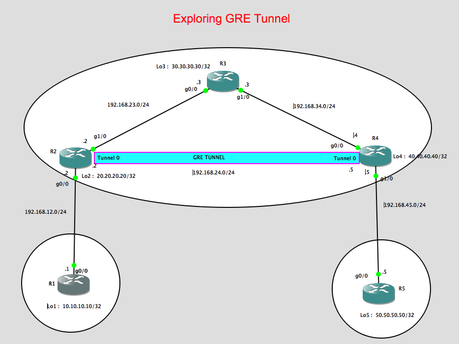
Some considerations for this lab:
1. R2, R3, R4 will be running OSPF as the IGP to make the loopbacks of both both R2 and R4 reachable.
2. The loopbacks of R2 and R4 will be use as the Tunnel source / Tunnel destinations, respectively.
3. IBGP will be run between R2 and R4 using the tunnel ip address in order to learned the prefix advertise by R1 (Loopback 1 IP address of 10.10.10.10/32) known to R5. In the same manner, we want that R1 will learn about 50.50.50.50/32 via BGP.
4. Configure next-hop-self on both R2 and R4. Since by default BGP routers will not change the next-hop ip address it learned from its BGP neighbours, the next-hop-self is required for both R2 and R4 so that the prefix that they learned from R1 and R5, respectively, will be updated with the correct next-hop ip address.
5. Configure GRE Tunnel between R2 and R4
Let me show the configurations for each device:
R1 Configurations:
R1#show run | sec router
router bgp 1
no synchronization
bgp log-neighbor-changes
network 10.10.10.10 mask 255.255.255.255
neighbor 192.168.12.2 remote-as 234
no auto-summary
R1#
R2 Configurations:
R2#show run | sec router
router ospf 1
log-adjacency-changes
network 20.20.20.20 0.0.0.0 area 0
network 192.168.23.0 0.0.0.255 area 0
R2#show run | sec router
router bgp 234
no synchronization
bgp log-neighbor-changes
network 20.20.20.20 mask 255.255.255.255
neighbor 192.168.12.1 remote-as 1
no auto-summary
p.p1 {margin: 0.0px 0.0px 0.0px 0.0px; font: 11.0px Menlo; color: #000000; background-color: #ffffff} span.s1 {font-variant-ligatures: no-common-ligatures}
R2#
R3 Configurations:
p.p1 {margin: 0.0px 0.0px 0.0px 0.0px; font: 11.0px Menlo; color: #000000; background-color: #ffffff} span.s1 {font-variant-ligatures: no-common-ligatures}
R3#show run | sec router
router ospf 1
log-adjacency-changes
network 192.168.23.0 0.0.0.255 area 0
network 192.168.34.0 0.0.0.255 area 0
R3#
R4 Configurations:
p.p1 {margin: 0.0px 0.0px 0.0px 0.0px; font: 11.0px Menlo; color: #000000; background-color: #ffffff} span.s1 {font-variant-ligatures: no-common-ligatures}
R4#show run | sec router
router ospf 1
log-adjacency-changes
network 40.40.40.40 0.0.0.0 area 0
network 192.168.34.0 0.0.0.255 area 0
R4#show run | sec router
router bgp 234
no synchronization
bgp log-neighbor-changes
network 40.40.40.40 mask 255.255.255.255
neighbor 192.168.45.5 remote-as 5
no auto-summary
R4#
R5 Configurations:
R5#show run | sec router
router bgp 5
no synchronization
bgp log-neighbor-changes
network 50.50.50.50 mask 255.255.255.255
neighbor 192.168.45.4 remote-as 234
no auto-summary
p.p1 {margin: 0.0px 0.0px 0.0px 0.0px; font: 11.0px Menlo; color: #000000; background-color: #ffffff} span.s1 {font-variant-ligatures: no-common-ligatures}
R5#
eBGP is established between R1 and R2:
R1#show ip bgp summary
BGP router identifier 10.10.10.10, local AS number 1
BGP table version is 5, main routing table version 5
4 network entries using 480 bytes of memory
4 path entries using 208 bytes of memory
4/4 BGP path/bestpath attribute entries using 496 bytes of memory
2 BGP AS-PATH entries using 48 bytes of memory
0 BGP route-map cache entries using 0 bytes of memory
0 BGP filter-list cache entries using 0 bytes of memory
BGP using 1232 total bytes of memory
BGP activity 4/0 prefixes, 4/0 paths, scan interval 60 secs
Neighbor V AS MsgRcvd MsgSent TblVer InQ OutQ Up/Down State/PfxRcd
192.168.12.2 4 234 102 101 5 0 0 01:27:28 3
p.p1 {margin: 0.0px 0.0px 0.0px 0.0px; font: 11.0px Menlo; color: #000000; background-color: #ffffff} p.p2 {margin: 0.0px 0.0px 0.0px 0.0px; font: 11.0px Menlo; color: #000000; background-color: #ffffff; min-height: 13.0px} span.s1 {font-variant-ligatures: no-common-ligatures}
R1#
eBGP is established between R2 and R1 as shown below:
R2#show ip bgp summary
BGP router identifier 20.20.20.20, local AS number 234
BGP table version is 6, main routing table version 6
4 network entries using 480 bytes of memory
4 path entries using 208 bytes of memory
4/4 BGP path/bestpath attribute entries using 496 bytes of memory
2 BGP AS-PATH entries using 48 bytes of memory
0 BGP route-map cache entries using 0 bytes of memory
0 BGP filter-list cache entries using 0 bytes of memory
BGP using 1232 total bytes of memory
BGP activity 4/0 prefixes, 4/0 paths, scan interval 60 secs
Neighbor V AS MsgRcvd MsgSent TblVer InQ OutQ Up/Down State/PfxRcd
192.168.12.1 4 1 108 109 6 0 0 01:33:56 1
p.p1 {margin: 0.0px 0.0px 0.0px 0.0px; font: 11.0px Menlo; color: #000000; background-color: #ffffff} p.p2 {margin: 0.0px 0.0px 0.0px 0.0px; font: 11.0px Menlo; color: #000000; background-color: #ffffff; min-height: 13.0px} span.s1 {font-variant-ligatures: no-common-ligatures}
R2#
Also OSPF neighbour is formed between R2 and R3 through the loopback address.
R2#show ip ospf neighbor
Neighbor ID Pri State Dead Time Address Interface
30.30.30.30 1 FULL/BDR 00:00:37 192.168.23.3 GigabitEthernet1/0
p.p1 {margin: 0.0px 0.0px 0.0px 0.0px; font: 11.0px Menlo; color: #000000; background-color: #ffffff} p.p2 {margin: 0.0px 0.0px 0.0px 0.0px; font: 11.0px Menlo; color: #000000; background-color: #ffffff; min-height: 13.0px} span.s1 {font-variant-ligatures: no-common-ligatures}
R2#
Similarly R3 are forming the OSPF neighbours with R2 and R4:
R3#show ip ospf neighbor
Neighbor ID Pri State Dead Time Address Interface
40.40.40.40 1 FULL/DR 00:00:37 192.168.34.4 GigabitEthernet1/0
20.20.20.20 1 FULL/DR 00:00:37 192.168.23.2 GigabitEthernet0/0
p.p1 {margin: 0.0px 0.0px 0.0px 0.0px; font: 11.0px Menlo; color: #000000; background-color: #ffffff} p.p2 {margin: 0.0px 0.0px 0.0px 0.0px; font: 11.0px Menlo; color: #000000; background-color: #ffffff; min-height: 13.0px} span.s1 {font-variant-ligatures: no-common-ligatures}
R3#
For R4, we can see below that OSPF is formed towards R3 while eBGP is formed towards R5.
R4#show ip ospf neighbor
Neighbor ID Pri State Dead Time Address Interface
30.30.30.30 1 FULL/BDR 00:00:31 192.168.34.3 GigabitEthernet0/0
R4#
eBGP between R4 and R5:
R4#show ip bgp summary
BGP router identifier 40.40.40.40, local AS number 234
BGP table version is 6, main routing table version 6
4 network entries using 480 bytes of memory
4 path entries using 208 bytes of memory
4/4 BGP path/bestpath attribute entries using 496 bytes of memory
2 BGP AS-PATH entries using 48 bytes of memory
0 BGP route-map cache entries using 0 bytes of memory
0 BGP filter-list cache entries using 0 bytes of memory
BGP using 1232 total bytes of memory
BGP activity 4/0 prefixes, 4/0 paths, scan interval 60 secs
Neighbor V AS MsgRcvd MsgSent TblVer InQ OutQ Up/Down State/PfxRcd
192.168.45.5 4 5 99 100 6 0 0 01:26:15 1
p.p1 {margin: 0.0px 0.0px 0.0px 0.0px; font: 11.0px Menlo; color: #000000; background-color: #ffffff} p.p2 {margin: 0.0px 0.0px 0.0px 0.0px; font: 11.0px Menlo; color: #000000; background-color: #ffffff; min-height: 13.0px} span.s1 {font-variant-ligatures: no-common-ligatures}
R4#
Looking at R5, we can observed thart eBGP is also formed towards R4:
R5#show ip bgp summary
BGP router identifier 50.50.50.50, local AS number 5
BGP table version is 5, main routing table version 5
4 network entries using 480 bytes of memory
4 path entries using 208 bytes of memory
4/4 BGP path/bestpath attribute entries using 496 bytes of memory
2 BGP AS-PATH entries using 48 bytes of memory
0 BGP route-map cache entries using 0 bytes of memory
0 BGP filter-list cache entries using 0 bytes of memory
BGP using 1232 total bytes of memory
BGP activity 4/0 prefixes, 4/0 paths, scan interval 60 secs
Neighbor V AS MsgRcvd MsgSent TblVer InQ OutQ Up/Down State/PfxRcd
192.168.45.4 4 234 103 102 5 0 0 01:28:48 3
p.p1 {margin: 0.0px 0.0px 0.0px 0.0px; font: 11.0px Menlo; color: #000000; background-color: #ffffff} p.p2 {margin: 0.0px 0.0px 0.0px 0.0px; font: 11.0px Menlo; color: #000000; background-color: #ffffff; min-height: 13.0px} span.s1 {font-variant-ligatures: no-common-ligatures}
R5#
Now here’s the interesting part, we need to build the GRE tunnels between R2 and R4 but we need to ensure that loopback interface of both R2 and R4 is reachable.
I would expect that the loopback will be reachable via OSPF on both routers. Let’s check the below verifications:
R2#show ip route ospf
Codes: L – local, C – connected, S – static, R – RIP, M – mobile, B – BGP
D – EIGRP, EX – EIGRP external, O – OSPF, IA – OSPF inter area
N1 – OSPF NSSA external type 1, N2 – OSPF NSSA external type 2
E1 – OSPF external type 1, E2 – OSPF external type 2
i – IS-IS, su – IS-IS summary, L1 – IS-IS level-1, L2 – IS-IS level-2
ia – IS-IS inter area, * – candidate default, U – per-user static route
o – ODR, P – periodic downloaded static route, + – replicated route
Gateway of last resort is not set
40.0.0.0/32 is subnetted, 1 subnets
O 40.40.40.40 [110/3] via 192.168.23.3, 01:27:02, GigabitEthernet1/0
O 192.168.34.0/24 [110/2] via 192.168.23.3, 01:29:28, GigabitEthernet1/0
R2#
R2#ping 40.40.40.40 source 20.20.20.20
Type escape sequence to abort.
Sending 5, 100-byte ICMP Echos to 40.40.40.40, timeout is 2 seconds:
Packet sent with a source address of 20.20.20.20
!!!!!
Success rate is 100 percent (5/5), round-trip min/avg/max = 16/28/44 ms
p.p1 {margin: 0.0px 0.0px 0.0px 0.0px; font: 11.0px Menlo; color: #000000; background-color: #ffffff} p.p2 {margin: 0.0px 0.0px 0.0px 0.0px; font: 11.0px Menlo; color: #000000; background-color: #ffffff; min-height: 13.0px} span.s1 {font-variant-ligatures: no-common-ligatures}
R2#
So as observed the loopback of R4 is reachable from R2.
Now Let’s configure the GRE Tunnels between R2 and R4:
R2#show run int tunnel 0
Building configuration…
Current configuration : 126 bytes
!
interface Tunnel0
ip address 192.168.24.2 255.255.255.0
tunnel source 20.20.20.20
tunnel destination 40.40.40.40
p.p1 {margin: 0.0px 0.0px 0.0px 0.0px; font: 11.0px Menlo; color: #000000; background-color: #ffffff} p.p2 {margin: 0.0px 0.0px 0.0px 0.0px; font: 11.0px Menlo; color: #000000; background-color: #ffffff; min-height: 13.0px} span.s1 {font-variant-ligatures: no-common-ligatures}
!
R4#show run int tunnel 0
Building configuration…
Current configuration : 126 bytes
!
interface Tunnel0
ip address 192.168.24.4 255.255.255.0
tunnel source 40.40.40.40
tunnel destination 20.20.20.20
!
p.p1 {margin: 0.0px 0.0px 0.0px 0.0px; font: 11.0px Menlo; color: #000000; background-color: #ffffff} p.p2 {margin: 0.0px 0.0px 0.0px 0.0px; font: 11.0px Menlo; color: #000000; background-color: #ffffff; min-height: 13.0px} span.s1 {font-variant-ligatures: no-common-ligatures}
end
So as observed above, the tunnel source for R2 is its own loopback address and the destination is the loopback of R4. I have assigned the ip address on each tunnel as per the IP addressing design
which is 192.168.24.2/24 for R2 and 192.168.24.4/24 for R4.
Let’s verify the Tunnel interface status,
R2#show ip int brief
Interface IP-Address OK? Method Status Protocol
Ethernet0/0 unassigned YES unset administratively down down
GigabitEthernet0/0 192.168.12.2 YES manual up up
GigabitEthernet1/0 192.168.23.2 YES manual up up
Loopback2 20.20.20.20 YES manual up up
Tunnel0 192.168.24.2 YES manual up up
p.p1 {margin: 0.0px 0.0px 0.0px 0.0px; font: 11.0px Menlo; color: #000000; background-color: #ffffff} span.s1 {font-variant-ligatures: no-common-ligatures}
R2#
R4#show ip int brief
Interface IP-Address OK? Method Status Protocol
Ethernet0/0 unassigned YES unset administratively down down
GigabitEthernet0/0 192.168.34.4 YES manual up up
GigabitEthernet1/0 192.168.45.4 YES manual up up
Loopback4 40.40.40.40 YES manual up up
Tunnel0 192.168.24.4 YES manual up up
p.p1 {margin: 0.0px 0.0px 0.0px 0.0px; font: 11.0px Menlo; color: #000000; background-color: #ffffff} span.s1 {font-variant-ligatures: no-common-ligatures}
R4#
As a test, i can ping the tunnel address of R4 from R2 as shown below,
R2#ping 192.168.24.4 source 192.168.24.2
Type escape sequence to abort.
Sending 5, 100-byte ICMP Echos to 192.168.24.4, timeout is 2 seconds:
Packet sent with a source address of 192.168.24.2
!!!!!
Success rate is 100 percent (5/5), round-trip min/avg/max = 16/27/32 ms
p.p1 {margin: 0.0px 0.0px 0.0px 0.0px; font: 11.0px Menlo; color: #000000; background-color: #ffffff} p.p2 {margin: 0.0px 0.0px 0.0px 0.0px; font: 11.0px Menlo; color: #000000; background-color: #ffffff; min-height: 13.0px} span.s1 {font-variant-ligatures: no-common-ligatures}
R2#
Now its time to configured iBGP between R2 and R4 so that the prefix advertise by R1 and R5 will be reachable.
p.p1 {margin: 0.0px 0.0px 0.0px 0.0px; font: 11.0px Menlo; color: #000000; background-color: #ffffff} span.s1 {font-variant-ligatures: no-common-ligatures}
R2#show run | sec router
router bgp 234
no synchronization
bgp log-neighbor-changes
network 20.20.20.20 mask 255.255.255.255
neighbor 192.168.12.1 remote-as 1
neighbor 192.168.24.4 remote-as 234
neighbor 192.168.24.4 next-hop-self
p.p1 {margin: 0.0px 0.0px 0.0px 0.0px; font: 11.0px Menlo; color: #000000; background-color: #ffffff} span.s1 {font-variant-ligatures: no-common-ligatures}
no auto-summary
R4#show run | sec router
router bgp 234
no synchronization
bgp log-neighbor-changes
network 40.40.40.40 mask 255.255.255.255
neighbor 192.168.24.2 remote-as 234
neighbor 192.168.24.2 next-hop-self
neighbor 192.168.45.5 remote-as 5
p.p1 {margin: 0.0px 0.0px 0.0px 0.0px; font: 11.0px Menlo; color: #000000; background-color: #ffffff} span.s1 {font-variant-ligatures: no-common-ligatures}
no auto-summary
As seen above, I have configured iBGP between R2 and R4. Let’s try to check the BGP status and the advertised/received routes:
R2#show ip bgp summary
BGP router identifier 20.20.20.20, local AS number 234
BGP table version is 6, main routing table version 6
4 network entries using 480 bytes of memory
4 path entries using 208 bytes of memory
4/4 BGP path/bestpath attribute entries using 496 bytes of memory
2 BGP AS-PATH entries using 48 bytes of memory
0 BGP route-map cache entries using 0 bytes of memory
0 BGP filter-list cache entries using 0 bytes of memory
BGP using 1232 total bytes of memory
BGP activity 4/0 prefixes, 4/0 paths, scan interval 60 secs
Neighbor V AS MsgRcvd MsgSent TblVer InQ OutQ Up/Down State/PfxRcd
192.168.12.1 4 1 124 125 6 0 0 01:48:49 1
192.168.24.4 4 234 108 106 6 0 0 01:28:55 2
p.p1 {margin: 0.0px 0.0px 0.0px 0.0px; font: 11.0px Menlo; color: #000000; background-color: #ffffff} p.p2 {margin: 0.0px 0.0px 0.0px 0.0px; font: 11.0px Menlo; color: #000000; background-color: #ffffff; min-height: 13.0px} span.s1 {font-variant-ligatures: no-common-ligatures}
R2#
R4#show ip bgp summary
BGP router identifier 40.40.40.40, local AS number 234
BGP table version is 6, main routing table version 6
4 network entries using 480 bytes of memory
4 path entries using 208 bytes of memory
4/4 BGP path/bestpath attribute entries using 496 bytes of memory
2 BGP AS-PATH entries using 48 bytes of memory
0 BGP route-map cache entries using 0 bytes of memory
0 BGP filter-list cache entries using 0 bytes of memory
BGP using 1232 total bytes of memory
BGP activity 4/0 prefixes, 4/0 paths, scan interval 60 secs
Neighbor V AS MsgRcvd MsgSent TblVer InQ OutQ Up/Down State/PfxRcd
192.168.24.2 4 234 106 109 6 0 0 01:29:26 2
192.168.45.5 4 5 117 118 6 0 0 01:43:00 1
p.p1 {margin: 0.0px 0.0px 0.0px 0.0px; font: 11.0px Menlo; color: #000000; background-color: #ffffff} p.p2 {margin: 0.0px 0.0px 0.0px 0.0px; font: 11.0px Menlo; color: #000000; background-color: #ffffff; min-height: 13.0px} span.s1 {font-variant-ligatures: no-common-ligatures}
R4#
Let’s check the prefix advertise by R2 and R4 by this time:
R2#show ip route bgp
Codes: L – local, C – connected, S – static, R – RIP, M – mobile, B – BGP
D – EIGRP, EX – EIGRP external, O – OSPF, IA – OSPF inter area
N1 – OSPF NSSA external type 1, N2 – OSPF NSSA external type 2
E1 – OSPF external type 1, E2 – OSPF external type 2
i – IS-IS, su – IS-IS summary, L1 – IS-IS level-1, L2 – IS-IS level-2
ia – IS-IS inter area, * – candidate default, U – per-user static route
o – ODR, P – periodic downloaded static route, + – replicated route
Gateway of last resort is not set
10.0.0.0/32 is subnetted, 1 subnets
B 10.10.10.10 [20/0] via 192.168.12.1, 01:50:51
50.0.0.0/32 is subnetted, 1 subnets
B 50.50.50.50 [200/0] via 192.168.24.4, 01:28:45
p.p1 {margin: 0.0px 0.0px 0.0px 0.0px; font: 11.0px Menlo; color: #000000; background-color: #ffffff} p.p2 {margin: 0.0px 0.0px 0.0px 0.0px; font: 11.0px Menlo; color: #000000; background-color: #ffffff; min-height: 13.0px} span.s1 {font-variant-ligatures: no-common-ligatures}
R2#
With the ” next-hop-self “ configured on R2, we can see that the next hop address to reach 50.50.50.50/32 is via the tunnel ip address of R4. R4 have changed this next-hop ip address when it advertise the prefix to R2.
As we can see below the next hop IP address learned by R4 with the prefix 50.50.50.50/32 is 192.168.45.5 which is R5.
R4#show ip route bgp
Codes: L – local, C – connected, S – static, R – RIP, M – mobile, B – BGP
D – EIGRP, EX – EIGRP external, O – OSPF, IA – OSPF inter area
N1 – OSPF NSSA external type 1, N2 – OSPF NSSA external type 2
E1 – OSPF external type 1, E2 – OSPF external type 2
i – IS-IS, su – IS-IS summary, L1 – IS-IS level-1, L2 – IS-IS level-2
ia – IS-IS inter area, * – candidate default, U – per-user static route
o – ODR, P – periodic downloaded static route, + – replicated route
Gateway of last resort is not set
10.0.0.0/32 is subnetted, 1 subnets
B 10.10.10.10 [200/0] via 192.168.24.2, 01:29:51
50.0.0.0/32 is subnetted, 1 subnets
B 50.50.50.50 [20/0] via 192.168.45.5, 01:45:08
p.p1 {margin: 0.0px 0.0px 0.0px 0.0px; font: 11.0px Menlo; color: #000000; background-color: #ffffff} p.p2 {margin: 0.0px 0.0px 0.0px 0.0px; font: 11.0px Menlo; color: #000000; background-color: #ffffff; min-height: 13.0px} span.s1 {font-variant-ligatures: no-common-ligatures}
R4#
So both routers are receiving the prefixes advertised by R1 and R5 and next hop change accordingly.
Thus we would expect that with the eBGP session established between R1 & R2 and R4 & R5, we could see on the BGP routing table the loopbacks for both R1 and R5.
R1#show ip route bgp
Codes: L – local, C – connected, S – static, R – RIP, M – mobile, B – BGP
D – EIGRP, EX – EIGRP external, O – OSPF, IA – OSPF inter area
N1 – OSPF NSSA external type 1, N2 – OSPF NSSA external type 2
E1 – OSPF external type 1, E2 – OSPF external type 2
i – IS-IS, su – IS-IS summary, L1 – IS-IS level-1, L2 – IS-IS level-2
ia – IS-IS inter area, * – candidate default, U – per-user static route
o – ODR, P – periodic downloaded static route, + – replicated route
Gateway of last resort is not set
20.0.0.0/32 is subnetted, 1 subnets
B 20.20.20.20 [20/0] via 192.168.12.2, 07:07:11
40.0.0.0/32 is subnetted, 1 subnets
B 40.40.40.40 [20/0] via 192.168.12.2, 06:47:34
50.0.0.0/32 is subnetted, 1 subnets
B 50.50.50.50 [20/0] via 192.168.12.2, 06:45:22
p.p1 {margin: 0.0px 0.0px 0.0px 0.0px; font: 11.0px Menlo; color: #000000; background-color: #ffffff} p.p2 {margin: 0.0px 0.0px 0.0px 0.0px; font: 11.0px Menlo; color: #000000; background-color: #ffffff; min-height: 13.0px} span.s1 {font-variant-ligatures: no-common-ligatures}
R1#
As we see below, we can reach the loopback of R2 from R5 so this means we have established a working GRE Tunnels.
R5#ping 10.10.10.10 source 50.50.50.50
Type escape sequence to abort.
Sending 5, 100-byte ICMP Echos to 10.10.10.10, timeout is 2 seconds:
Packet sent with a source address of 50.50.50.50
!!!!!
Success rate is 100 percent (5/5), round-trip min/avg/max = 48/56/68 ms
R5#traceroute 10.10.10.10 source 50.50.50.50
Type escape sequence to abort.
Tracing the route to 10.10.10.10
1 192.168.45.4 12 msec 28 msec 24 msec
2 192.168.24.2 44 msec 12 msec 72 msec
3 192.168.12.1 48 msec 44 msec 56 msec
p.p1 {margin: 0.0px 0.0px 0.0px 0.0px; font: 11.0px Menlo; color: #000000; background-color: #ffffff} p.p2 {margin: 0.0px 0.0px 0.0px 0.0px; font: 11.0px Menlo; color: #000000; background-color: #ffffff; min-height: 13.0px} span.s1 {font-variant-ligatures: no-common-ligatures}
R5#
Take away for this lab:
1. IGP was used as the routing protocol to advertise the loopbacks in this case, OSPF is used.
2. We have decided to used BGP to advertise the prefix on R1 & R5 through the GRE tunnel devices ( R2 & R4).
3. Next-Hop-Self is necessary to advertised the prefix to the other side of the network otherwise reachability will not be established.
p.p1 {margin: 0.0px 0.0px 0.0px 0.0px; font: 11.0px Menlo; color: #000000; background-color: #ffffff} span.s1 {font-variant-ligatures: no-common-ligatures} p.p1 {margin: 0.0px 0.0px 0.0px 0.0px; font: 11.0px Menlo; color: #000000; background-color: #ffffff} span.s1 {font-variant-ligatures: no-common-ligatures} p.p1 {margin: 0.0px 0.0px 0.0px 0.0px; font: 11.0px Menlo; color: #000000; background-color: #ffffff} p.p2 {margin: 0.0px 0.0px 0.0px 0.0px; font: 11.0px Menlo; color: #000000; background-color: #ffffff; min-height: 13.0px} span.s1 {font-variant-ligatures: no-common-ligatures}
BGP Route Reflector
Notes:
- In the simplest of route-reflection designs, a central peering point is chosen for all devices in the iBGP domain, and all peers of this device are defined as clients
- BGP route reflectors, as defined in RFC 2796, are used in large-scale iBGP deployments to reduce the need for [n*(n-1)/2] fully meshed peerings
The route reflector can have three type of peerings:
- EBGP neighbor
- IBGP client neighbor
- BGP non-client neighbor
When a route reflector forwards a route, there are a couple of rules:
1. A route learned from an EBGP neighbor can be forwarded to another EBGP neighbor, a client and non-client.
2. A route learned from a client can be forwarded to another EBGP neighbor, client and non-client.
3. A route learned from a non client can be forwarded to another EBGP neighbor and client, but not to a non-client.
TOPOLOGY:

CONFIGURATIONS:
RR-Client1 BGP Configurations:
router bgp 1
no synchronization
bgp log-neighbor-changes
network 10.10.10.10 mask 255.255.255.255
neighbor 192.168.12.2 remote-as 1
no auto-summary
RR BGP Configurations:
router bgp 1
no synchronization
bgp log-neighbor-changes
network 192.168.12.0
network 192.168.23.0
neighbor 192.168.12.1 remote-as 1
neighbor 192.168.12.1 route-reflector-client
neighbor 192.168.23.3 remote-as 1
neighbor 192.168.23.3 route-reflector-client
no auto-summary
RR-Client2 BGP Configurations:
router bgp 1
no synchronization
bgp log-neighbor-changes
neighbor 192.168.12.2 remote-as 1
neighbor 192.168.23.2 remote-as 1
neighbor 192.168.23.2 route-reflector-client
no auto-summary
Verifications
RR-Client1#show ip route
Codes: L – local, C – connected, S – static, R – RIP, M – mobile, B – BGP
D – EIGRP, EX – EIGRP external, O – OSPF, IA – OSPF inter area
N1 – OSPF NSSA external type 1, N2 – OSPF NSSA external type 2
E1 – OSPF external type 1, E2 – OSPF external type 2
i – IS-IS, su – IS-IS summary, L1 – IS-IS level-1, L2 – IS-IS level-2
ia – IS-IS inter area, * – candidate default, U – per-user static route
o – ODR, P – periodic downloaded static route, + – replicated route
Gateway of last resort is not set
10.0.0.0/32 is subnetted, 1 subnets
C 10.10.10.10 is directly connected, Loopback0
192.168.12.0/24 is variably subnetted, 2 subnets, 2 masks
C 192.168.12.0/24 is directly connected, Serial4/0
L 192.168.12.1/32 is directly connected, Serial4/0
B 192.168.23.0/24 [200/0] via 192.168.12.2, 00:45:32
RR-Client1#show ip bgp summary
BGP router identifier 10.10.10.10, local AS number 1
BGP table version is 5, main routing table version 5
3 network entries using 360 bytes of memory
3 path entries using 156 bytes of memory
2/2 BGP path/bestpath attribute entries using 248 bytes of memory
0 BGP route-map cache entries using 0 bytes of memory
0 BGP filter-list cache entries using 0 bytes of memory
BGP using 764 total bytes of memory
BGP activity 3/0 prefixes, 3/0 paths, scan interval 60 secs
Neighbor V AS MsgRcvd MsgSent TblVer InQ OutQ Up/Down State/PfxRcd
192.168.12.2 4 1 65 63 5 0 0 00:53:30 2
RR-Client1#show ip bgp 10.10.10.10
BGP routing table entry for 10.10.10.10/32, version 2
Paths: (1 available, best #1, table default)
Advertised to update-groups:
2
Local
0.0.0.0 from 0.0.0.0 (10.10.10.10)
Origin IGP, metric 0, localpref 100, weight 32768, valid, sourced, local, best
RR-Client1#
Take away from RR – Route Reflector client:
- If a route-reflector sees a prefix that is coming from a Route-Reflector Client, they are tagged internally as being received from a client peer and can be advertise to other route-reflector peers.
RR#show ip bgp 10.10.10.10
BGP routing table entry for 10.10.10.10/32, version 2
Paths: (1 available, best #1, table default)
Advertised to update-groups:
3
Local, (Received from a RR-client)
192.168.12.1 from 192.168.12.1 (10.10.10.10)
Origin IGP, metric 0, localpref 100, valid, internal, best
- When a route is advertised, or “reflected,” from the route reflector to a client or non-client, BGP attributes such as the next-hop value are not updated:
RR#show ip bgp neighbors 192.168.23.3 advertised-routes
BGP table version is 4, local router ID is 22.22.22.22
Status codes: s suppressed, d damped, h history, * valid, > best, i – internal,
r RIB-failure, S Stale
Origin codes: i – IGP, e – EGP, ? – incomplete
Originating default network 0.0.0.0
Network Next Hop Metric LocPrf Weight Path
*>i10.10.10.10/32 192.168.12.1 0 100 0 i
*> 192.168.12.0 0.0.0.0 0 32768 i
*> 192.168.23.0 0.0.0.0 0 32768 i
Total number of prefixes 3
RR#
Take away from Route-Reflector Client2:
- RR-Client2 will also introduce another attribute called Originator which is the source of the prefix that is advertise. The Originator ID, is set by the route reflector as the BGP router-id of the neighbor from which it learned the prefix. If router-ID is not configured, it will select the highest loopback address.
- When any BGP speaker learns a route from an iBGP neighbor, and the Originator ID matches their own local router-id/loopback the route is discarded. This is why it is essential that the BGP router-id value be unique throughout the entire routing domain, just like in OSPF and EIGRP. This is BGP split horizon concepts. The IBGP split horizon rule was created to prevent loops, since our route reflector violates this rule we have to think of a new rule for loop prevention.
- RR-Client2 will introduce an attribute called Cluster list which will be the highest Loopback interface of Route-reflector Client.
- The Cluster List, contains the Cluster-IDs of the route reflectors that the route transited through in the network. Unless the bgp cluster-id command is manually configured under the BGP routing process, the value defaults to the router-id of the route reflector. If no router-id configured, it will used the highest loopback address.
RR-Client2#show ip bgp 10.10.10.10
BGP routing table entry for 10.10.10.10/32, version 17
Paths: (1 available, no best path)
Not advertised to any peer
Local
192.168.12.1 (inaccessible) from 192.168.23.2 (100.100.100.100)
Origin IGP, metric 0, localpref 100, valid, internal
Originator: 10.10.10.10, Cluster list: 100.100.100.100
RR-Client2#
RR-Client2#ping 10.10.10.10
Type escape sequence to abort.
Sending 5, 100-byte ICMP Echos to 10.10.10.10, timeout is 2 seconds:
!!!!!
Success rate is 100 percent (5/5), round-trip min/avg/max = 20/28/44 ms
RR-Client2#
BGP Confederations Explained
Some important concepts:
bgp confederation identifier command to tell BGP the main AS number.
bgp confederation peers command to configure all other sub-AS numbers
confed-internal tagged which means that it came from an IBGP router within the same sub-AS.
confed-external tagged which means that it came from another Sub-AS within the confederations.
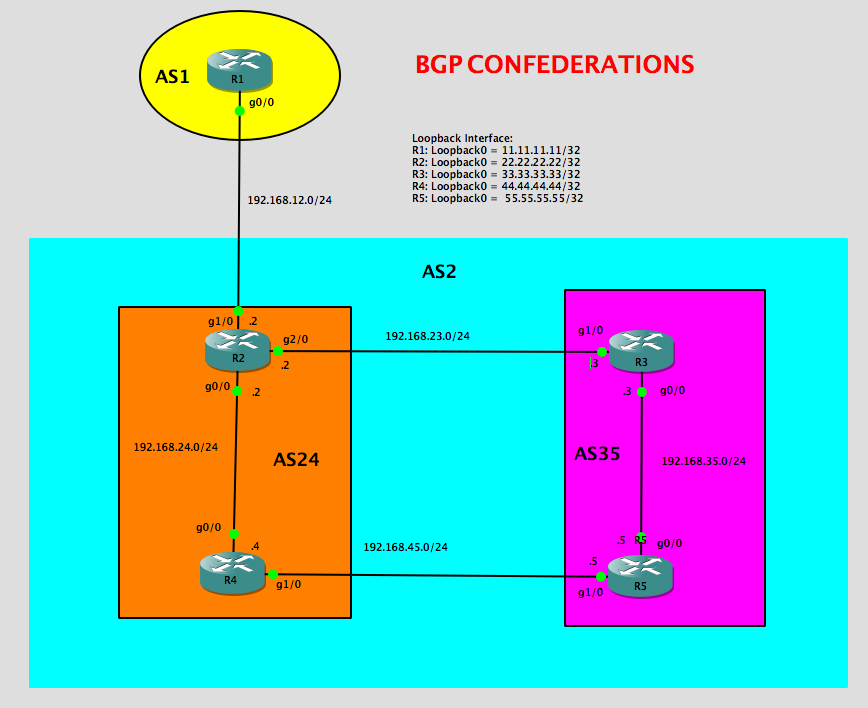
Configurations Section:
R1 Configs:
R1#show run | sec bgp
ipv6 multicast rpf use-bgp
router bgp 1
bgp log-neighbor-changes
network 11.11.11.11 mask 255.255.255.255
neighbor 192.168.12.2 remote-as 2
R1#
R2 Configs:
R2#show run | sec ospf
router ospf 1
network 22.22.22.22 0.0.0.0 area 0
network 192.168.23.0 0.0.0.255 area 0
network 192.168.24.0 0.0.0.255 area 0
R2#
R2#show run | sec bgp
ipv6 multicast rpf use-bgp
router bgp 24
bgp log-neighbor-changes
bgp confederation identifier 2
bgp confederation peers 35
network 22.22.22.22 mask 255.255.255.255
network 192.168.12.0
neighbor 192.168.12.1 remote-as 1
neighbor 33.33.33.33 remote-as 35
neighbor 33.33.33.33 ebgp-multihop 2
neighbor 33.33.33.33 update-source Loopback0
neighbor 44.44.44.44 remote-as 24
neighbor 44.44.44.44 update-source Loopback0
R2#
R3 Configs:
R3#show run | sec ospf
router ospf 1
network 33.33.33.33 0.0.0.0 area 0
network 192.168.23.0 0.0.0.255 area 0
network 192.168.35.0 0.0.0.255 area 0
R3#
R3#show run | sec bgp
ipv6 multicast rpf use-bgp
router bgp 35
bgp log-neighbor-changes
bgp confederation identifier 2
bgp confederation peers 24
neighbor 22.22.22.22 remote-as 24
neighbor 22.22.22.22 ebgp-multihop 2
neighbor 22.22.22.22 update-source Loopback0
neighbor 55.55.55.55 remote-as 35
neighbor 55.55.55.55 update-source Loopback0
R3#
R4 Configs:
R4#show run | sec ospf
router ospf 1
network 44.44.44.44 0.0.0.0 area 0
network 192.168.24.0 0.0.0.255 area 0
network 192.168.45.0 0.0.0.255 area 0
R4#
R4#show run | sec bgp
ipv6 multicast rpf use-bgp
router bgp 24
bgp log-neighbor-changes
bgp confederation identifier 2
bgp confederation peers 35
neighbor 22.22.22.22 remote-as 24
neighbor 22.22.22.22 update-source Loopback0
neighbor 55.55.55.55 remote-as 35
neighbor 55.55.55.55 ebgp-multihop 255
neighbor 55.55.55.55 update-source Loopback0
R4#
R5 Configs:
R5#show run | sec ospf
router ospf 1
network 55.55.55.55 0.0.0.0 area 0
network 192.168.35.0 0.0.0.255 area 0
network 192.168.45.0 0.0.0.255 area 0
R5#
R5#show run | sec bgp
ipv6 multicast rpf use-bgp
router bgp 35
bgp log-neighbor-changes
network 55.55.55.55 mask 255.255.255.255
neighbor 33.33.33.33 remote-as 35
neighbor 33.33.33.33 update-source Loopback0
neighbor 44.44.44.44 remote-as 24
neighbor 44.44.44.44 ebgp-multihop 2
neighbor 44.44.44.44 update-source Loopback0
R5#
Verifications Sections:
R1#show ip bgp summary
BGP router identifier 11.11.11.11, local AS number 1
BGP table version is 6, main routing table version 6
4 network entries using 576 bytes of memory
4 path entries using 320 bytes of memory
3/3 BGP path/bestpath attribute entries using 408 bytes of memory
1 BGP AS-PATH entries using 24 bytes of memory
0 BGP route-map cache entries using 0 bytes of memory
0 BGP filter-list cache entries using 0 bytes of memory
BGP using 1328 total bytes of memory
BGP activity 4/0 prefixes, 4/0 paths, scan interval 60 secs
Neighbor V AS MsgRcvd MsgSent TblVer InQ OutQ Up/Down State/PfxRcd
22.22.22.22 4 2 36 33 6 0 0 00:26:53 3
R1#
R2#show ip bgp summary
BGP router identifier 22.22.22.22, local AS number 24
BGP table version is 6, main routing table version 6
4 network entries using 576 bytes of memory
4 path entries using 320 bytes of memory
3/3 BGP path/bestpath attribute entries using 408 bytes of memory
2 BGP AS-PATH entries using 48 bytes of memory
0 BGP route-map cache entries using 0 bytes of memory
0 BGP filter-list cache entries using 0 bytes of memory
BGP using 1352 total bytes of memory
BGP activity 4/0 prefixes, 5/1 paths, scan interval 60 secs
Neighbor V AS MsgRcvd MsgSent TblVer InQ OutQ Up/Down State/PfxRcd
11.11.11.11 4 1 34 37 6 0 0 00:27:53 1
33.33.33.33 4 35 54 57 6 0 0 00:45:44 1
44.44.44.44 4 24 67 68 6 0 0 00:56:01 0
R2#
R3#show ip bgp summary
BGP router identifier 33.33.33.33, local AS number 35
BGP table version is 4, main routing table version 4
4 network entries using 576 bytes of memory
4 path entries using 320 bytes of memory
3/2 BGP path/bestpath attribute entries using 408 bytes of memory
2 BGP AS-PATH entries using 48 bytes of memory
0 BGP route-map cache entries using 0 bytes of memory
0 BGP filter-list cache entries using 0 bytes of memory
BGP using 1352 total bytes of memory
BGP activity 4/0 prefixes, 6/2 paths, scan interval 60 secs
Neighbor V AS MsgRcvd MsgSent TblVer InQ OutQ Up/Down State/PfxRcd
22.22.22.22 4 24 57 55 4 0 0 00:46:10 3
55.55.55.55 4 35 24 21 4 0 0 00:15:03 1
R3#
R4#show ip bgp summary
BGP router identifier 44.44.44.44, local AS number 24
BGP table version is 5, main routing table version 5
4 network entries using 576 bytes of memory
7 path entries using 560 bytes of memory
5/2 BGP path/bestpath attribute entries using 680 bytes of memory
3 BGP AS-PATH entries using 72 bytes of memory
0 BGP route-map cache entries using 0 bytes of memory
0 BGP filter-list cache entries using 0 bytes of memory
BGP using 1888 total bytes of memory
BGP activity 4/0 prefixes, 7/0 paths, scan interval 60 secs
Neighbor V AS MsgRcvd MsgSent TblVer InQ OutQ Up/Down State/PfxRcd
22.22.22.22 4 24 69 68 5 0 0 00:56:52 4
55.55.55.55 4 35 22 22 5 0 0 00:15:58 3
R4#
R5#show ip bgp summary
BGP router identifier 55.55.55.55, local AS number 35
BGP table version is 11, main routing table version 11
3 network entries using 432 bytes of memory
6 path entries using 480 bytes of memory
3/2 BGP path/bestpath attribute entries using 408 bytes of memory
2 BGP AS-PATH entries using 48 bytes of memory
0 BGP route-map cache entries using 0 bytes of memory
0 BGP filter-list cache entries using 0 bytes of memory
BGP using 1368 total bytes of memory
BGP activity 3/0 prefixes, 6/0 paths, scan interval 60 secs
Neighbor V AS MsgRcvd MsgSent TblVer InQ OutQ Up/Down State/PfxRcd
33.33.33.33 4 35 22 25 11 0 0 00:15:53 2
44.44.44.44 4 24 23 23 11 0 0 00:16:22 3
R5#
Routing Verifications:
R1#show ip bgp
BGP table version is 16, local router ID is 11.11.11.11
Status codes: s suppressed, d damped, h history, * valid, > best, i – internal,
r RIB-failure, S Stale, m multipath, b backup-path, f RT-Filter,
x best-external, a additional-path, c RIB-compressed,
Origin codes: i – IGP, e – EGP, ? – incomplete
RPKI validation codes: V valid, I invalid, N Not found
Network Next Hop Metric LocPrf Weight Path
*> 11.11.11.11/32 0.0.0.0 0 32768 i
*> 22.22.22.22/32 192.168.12.2 0 0 2 i
*> 55.55.55.55/32 192.168.12.2 0 2 I <<<<<<< RIB failures
r> 192.168.12.0 192.168.12.2 0 0 2 i
R1#
R2#show ip bgp
BGP table version is 9, local router ID is 22.22.22.22
Status codes: s suppressed, d damped, h history, * valid, > best, i – internal,
r RIB-failure, S Stale, m multipath, b backup-path, f RT-Filter,
x best-external, a additional-path, c RIB-compressed,
Origin codes: i – IGP, e – EGP, ? – incomplete
RPKI validation codes: V valid, I invalid, N Not found
Network Next Hop Metric LocPrf Weight Path
*> 11.11.11.11/32 192.168.12.1 0 0 1 i
*> 22.22.22.22/32 0.0.0.0 0 32768 i
r> 55.55.55.55/32 55.55.55.55 0 100 0 (35) i
*> 192.168.12.0 0.0.0.0 0 32768 i
R2#
Received Prefix as an External route via R1:
R2#show ip bgp 11.11.11.11
BGP routing table entry for 11.11.11.11/32, version 8
Paths: (1 available, best #1, table default)
Advertised to update-groups:
4 5
Refresh Epoch 1
1
192.168.12.1 from 192.168.12.1 (11.11.11.11)
Origin IGP, metric 0, localpref 100, valid, external, best
rx pathid: 0, tx pathid: 0x0
R2#
Prefix is received by R2 from R3 and is tagged with confed-external. This means that the route is learned from another Sub-AS within the confederations.
R2#show ip bgp 55.55.55.55
BGP routing table entry for 55.55.55.55/32, version 4
Paths: (1 available, best #1, table default, RIB-failure(17))
Advertised to update-groups:
5 7
Refresh Epoch 1
(35)
55.55.55.55 (metric 3) from 33.33.33.33 (33.33.33.33)
Origin IGP, metric 0, localpref 100, valid, confed-external, best
rx pathid: 0, tx pathid: 0x0
R2#
R3#show ip bgp
BGP table version is 16, local router ID is 33.33.33.33
Status codes: s suppressed, d damped, h history, * valid, > best, i – internal,
r RIB-failure, S Stale, m multipath, b backup-path, f RT-Filter,
x best-external, a additional-path, c RIB-compressed,
Origin codes: i – IGP, e – EGP, ? – incomplete
RPKI validation codes: V valid, I invalid, N Not found
Network Next Hop Metric LocPrf Weight Path
*> 11.11.11.11/32 192.168.12.1 0 100 0 (24) 1 i
r> 22.22.22.22/32 22.22.22.22 0 100 0 (24) i
r>i 55.55.55.55/32 55.55.55.55 0 100 0 i
*> 192.168.12.0 22.22.22.22 0 100 0 (24) i
R3#
R3 learned the Prefix11.11.11.11/32 from R2 , and AS Path have appended AS 24.
R3#show ip bgp 11.11.11.11
BGP routing table entry for 11.11.11.11/32, version 16
Paths: (1 available, best #1, table default)
Advertised to update-groups:
2
Refresh Epoch 1
(24) 1
192.168.12.1 (metric 2) from 22.22.22.22 (22.22.22.22)
Origin IGP, metric 0, localpref 100, valid, confed-external, best
rx pathid: 0, tx pathid: 0x0
R3#
R4 learned 11.11.11.11/32 from both R1 and R5. R1 tagged the prefix with confed-internalwhile R5 tagged the prefix as confed-external
R4#show ip bgp 11.11.11.11
BGP routing table entry for 11.11.11.11/32, version 14
Paths: (2 available, best #2, table default)
Advertised to update-groups:
2
Refresh Epoch 1
35 1
55.55.55.55 (metric 2) from 55.55.55.55 (55.55.55.55)
Origin IGP, localpref 100, valid, confed-external
rx pathid: 0, tx pathid: 0
Refresh Epoch 1
1
192.168.12.1 (metric 2) from 22.22.22.22 (22.22.22.22)
Origin IGP, metric 0, localpref 100, valid, confed-internal, best
rx pathid: 0, tx pathid: 0x0
R4#
From the BGP routing Information base, new BGP attribute is introduced which is the Confed_AS_Set which prepend the Confederation Sub-AS. For the case of prefix 11.11.11.11/32 , it was advertised from R1 with AS 1 and it was learned by R2
R4#show ip bgp
BGP table version is 14, local router ID is 44.44.44.44
Status codes: s suppressed, d damped, h history, * valid, > best, i – internal,
r RIB-failure, S Stale, m multipath, b backup-path, f RT-Filter,
x best-external, a additional-path, c RIB-compressed,
Origin codes: i – IGP, e – EGP, ? – incomplete
RPKI validation codes: V valid, I invalid, N Not found
Network Next Hop Metric LocPrf Weight Path
* 11.11.11.11/32 55.55.55.55 0 35 1 i
*>i 192.168.12.1 0 100 0 1 i
r 22.22.22.22/32 55.55.55.55 0 35 i
r>i 22.22.22.22 0 100 0 i
r>i 55.55.55.55/32 55.55.55.55 0 100 0 (35) i
r 55.55.55.55 0 0 35 i
* 192.168.12.0 55.55.55.55 0 35 i
*>i 22.22.22.22 0 100 0 i
OSPF : Traffic flow behavior with varying OSPF cost

This post is to check the behavior of the network with varying OSPF cost on the link between OSPF neighbors.
Configurations requirements:
1. Used OSPF as the IGP protocol between the three locations
2. Looopback 0 will be used to established OSPF neighbors.
3. Run IBGP between the routers and neighbors should be formed via Loopback 2.
4. Change the OSPF cost on SYDNEY link towards MANILA to 1000 and check the traffic flow from MANILA towards SYDNEY router loopback 2. Questions to ask here, is the IBGP peering between SYDNEY and MANILA resetted? Is MANILA sending the advertisement via SYDNEY after SYDNEY link is costed out?
5. Finally, apply an OSPF cost of 1000 on the MANILA link and check the traffic flow towards SYDNEY router loopback 2.
Router Configurations:
a. IGP (OSPF configurations):
SYDNEY Router:
SYDNEY#show run | sec ospf
router ospf 1
router-id 1.1.1.1
network 1.1.1.1 0.0.0.0 area 0
network 11.11.11.11 0.0.0.0 area 0
network 192.168.12.0 0.0.0.255 area 0
network 192.168.13.0 0.0.0.255 area 0
TOKYO Router
TOKYO#show run | sec ospf
router ospf 1
router-id 2.2.2.2
network 2.2.2.2 0.0.0.0 area 0
network 22.22.22.22 0.0.0.0 area 0
network 192.168.12.0 0.0.0.255 area 0
network 192.168.23.0 0.0.0.255 area 0
MANILA Router:
MANILA#show run | sec ospf
router ospf 1
router-id 3.3.3.3
network 3.3.3.3 0.0.0.0 area 0
network 33.33.33.33 0.0.0.0 area 0
network 192.168.13.0 0.0.0.255 area 0
network 192.168.23.0 0.0.0.255 area 0
As verified the OSPF Neighbors were all formed:
SYDNEY#show ip ospf neighbor
Neighbor ID Pri State Dead Time Address Interface
3.3.3.3 0 FULL/ – 00:00:39 192.168.13.3 Serial3/2
2.2.2.2 0 FULL/ – 00:00:34 192.168.12.2 Serial3/0
TOKYO#show ip ospf neighbor
Neighbor ID Pri State Dead Time Address Interface
3.3.3.3 0 FULL/ – 00:00:37 192.168.23.3 Serial3/1
1.1.1.1 0 FULL/ – 00:00:39 192.168.12.1 Serial3/0
TOKYO#
MANILA#show ip ospf neighbor
Neighbor ID Pri State Dead Time Address Interface
2.2.2.2 0 FULL/ – 00:00:37 192.168.23.2 Serial3/1
1.1.1.1 0 FULL/ – 00:00:34 192.168.13.1 Serial3/2
MANILA#
And as checked the loopback 2 interface were advertised via OSPF. This will be used for IBGP peerings.
TOKYO#show ip ospf route
OSPF Router with ID (2.2.2.2) (Process ID 1)
Base Topology (MTID 0)
Area BACKBONE(0)
Intra-area Route List
* 192.168.12.0/24, Intra, cost 64, area 0, Connected
via 192.168.12.2, Serial3/0
*> 192.168.13.0/24, Intra, cost 1064, area 0
via 192.168.12.1, Serial3/0
via 192.168.23.3, Serial3/1
* 192.168.23.0/24, Intra, cost 64, area 0, Connected
via 192.168.23.2, Serial3/1
*> 1.1.1.1/32, Intra, cost 65, area 0
via 192.168.12.1, Serial3/0
* 2.2.2.2/32, Intra, cost 1, area 0, Connected
via 2.2.2.2, Loopback0
*> 3.3.3.3/32, Intra, cost 65, area 0
via 192.168.23.3, Serial3/1
*> 11.11.11.11/32, Intra, cost 65, area 0
via 192.168.12.1, Serial3/0
* 22.22.22.22/32, Intra, cost 1, area 0, Connected
via 22.22.22.22, Loopback2
*> 33.33.33.33/32, Intra, cost 65, area 0
via 192.168.23.3, Serial3/1
TOKYO#
MANILA#show ip ospf route
OSPF Router with ID (3.3.3.3) (Process ID 1)
Base Topology (MTID 0)
Area BACKBONE(0)
Intra-area Route List
*> 192.168.12.0/24, Intra, cost 128, area 0
via 192.168.23.2, Serial3/1
* 192.168.13.0/24, Intra, cost 1000, area 0, Connected
via 192.168.13.3, Serial3/2
* 192.168.23.0/24, Intra, cost 64, area 0, Connected
via 192.168.23.3, Serial3/1
*> 1.1.1.1/32, Intra, cost 129, area 0
via 192.168.23.2, Serial3/1
*> 2.2.2.2/32, Intra, cost 65, area 0
via 192.168.23.2, Serial3/1
* 3.3.3.3/32, Intra, cost 1, area 0, Connected
via 3.3.3.3, Loopback0
*> 11.11.11.11/32, Intra, cost 129, area 0
via 192.168.23.2, Serial3/1
*> 22.22.22.22/32, Intra, cost 65, area 0
via 192.168.23.2, Serial3/1
* 33.33.33.33/32, Intra, cost 1, area 0, Connected
via 33.33.33.33, Loopback2
MANILA#
SYDNEY#show ip ospf route
OSPF Router with ID (1.1.1.1) (Process ID 1)
Base Topology (MTID 0)
Area BACKBONE(0)
Intra-area Route List
* 192.168.12.0/24, Intra, cost 64, area 0, Connected
via 192.168.12.1, Serial3/0
* 192.168.13.0/24, Intra, cost 1000, area 0, Connected
via 192.168.13.1, Serial3/2
*> 192.168.23.0/24, Intra, cost 128, area 0
via 192.168.12.2, Serial3/0
* 1.1.1.1/32, Intra, cost 1, area 0, Connected
via 1.1.1.1, Loopback0
*> 2.2.2.2/32, Intra, cost 65, area 0
via 192.168.12.2, Serial3/0
*> 3.3.3.3/32, Intra, cost 129, area 0
via 192.168.12.2, Serial3/0
* 11.11.11.11/32, Intra, cost 1, area 0, Connected
via 11.11.11.11, Loopback2
*> 22.22.22.22/32, Intra, cost 65, area 0
via 192.168.12.2, Serial3/0
*> 33.33.33.33/32, Intra, cost 129, area 0
via 192.168.12.2, Serial3/0
SYDNEY#
With the presence of the Loopback 2 addresses into the OSPF routing table , it ensures reachability of BGP TCP sessions required in order to formed BGP neighbors.
Now, I’m configuring the IBGP between routers:
SYDNEY#show run | sec bgp
ipv6 multicast rpf use-bgp
router bgp 1
bgp log-neighbor-changes
neighbor 22.22.22.22 remote-as 1
neighbor 22.22.22.22 update-source Loopback2
neighbor 33.33.33.33 remote-as 1
neighbor 33.33.33.33 update-source Loopback2
SYDNEY#
MANILA#show run | sec bgp
ipv6 multicast rpf use-bgp
router bgp 1
bgp log-neighbor-changes
neighbor 11.11.11.11 remote-as 1
neighbor 11.11.11.11 update-source Loopback2
neighbor 22.22.22.22 remote-as 1
neighbor 22.22.22.22 update-source Loopback2
MANILA#
TOKYO#show run | sec bgp
ipv6 multicast rpf use-bgp
router bgp 1
bgp log-neighbor-changes
neighbor 11.11.11.11 remote-as 1
neighbor 11.11.11.11 update-source Loopback2
neighbor 33.33.33.33 remote-as 1
neighbor 33.33.33.33 update-source Loopback2
TOKYO#
Let’s verify the BGP neighbors formed:
TOKYO#show ip bgp summary
BGP router identifier 22.22.22.22, local AS number 1
BGP table version is 1, main routing table version 1
Neighbor V AS MsgRcvd MsgSent TblVer InQ OutQ Up/Down State/PfxRcd
11.11.11.11 4 1 36 36 1 0 0 00:30:27 0
33.33.33.33 4 1 36 36 1 0 0 00:30:28 0
TOKYO#
MANILA#show ip bgp summary
BGP router identifier 33.33.33.33, local AS number 1
BGP table version is 1, main routing table version 1
Neighbor V AS MsgRcvd MsgSent TblVer InQ OutQ Up/Down State/PfxRcd
11.11.11.11 4 1 36 37 1 0 0 00:30:53 0
22.22.22.22 4 1 37 36 1 0 0 00:30:51 0
MANILA#
SYDNEY#show ip bgp summary
BGP router identifier 11.11.11.11, local AS number 1
BGP table version is 1, main routing table version 1
Neighbor V AS MsgRcvd MsgSent TblVer InQ OutQ Up/Down State/PfxRcd
22.22.22.22 4 1 37 37 1 0 0 00:31:13 0
33.33.33.33 4 1 37 37 1 0 0 00:31:15 0
SYDNEY#
The default OSPF cost is calculated as Cost = Reference Bandwidth/Interface Bandwidth . With my set up above, i notice that the default OSPF cost is 64 on all the 3 OSPF neighbors as I’m connecting them via a serial links with a bandwidth of 1.544 Mbps.
Example below from TOKYO router
TOKYO#show ip ospf interface s3/0
Serial3/0 is up, line protocol is up
Internet Address 192.168.12.2/24, Area 0, Attached via Network Statement
Process ID 1, Router ID 2.2.2.2, Network Type POINT_TO_POINT, Cost: 64
Topology-MTID Cost Disabled Shutdown Topology Name
0 64 no no Base
Transmit Delay is 1 sec, State POINT_TO_POINT
Timer intervals configured, Hello 10, Dead 40, Wait 40, Retransmit 5
oob-resync timeout 40
Hello due in 00:00:03
Supports Link-local Signaling (LLS)
Cisco NSF helper support enabled
IETF NSF helper support enabled
Index 3/3, flood queue length 0
Next 0x0(0)/0x0(0)
Last flood scan length is 1, maximum is 1
Last flood scan time is 4 msec, maximum is 4 msec
Neighbor Count is 1, Adjacent neighbor count is 1
Adjacent with neighbor 1.1.1.1
Suppress hello for 0 neighbor(s)
TOKYO#show ip ospf interface s3/1
Serial3/1 is up, line protocol is up
Internet Address 192.168.23.2/24, Area 0, Attached via Network Statement
Process ID 1, Router ID 2.2.2.2, Network Type POINT_TO_POINT, Cost: 64
Topology-MTID Cost Disabled Shutdown Topology Name
0 64 no no Base
Transmit Delay is 1 sec, State POINT_TO_POINT
Timer intervals configured, Hello 10, Dead 40, Wait 40, Retransmit 5
oob-resync timeout 40
Hello due in 00:00:02
Supports Link-local Signaling (LLS)
Cisco NSF helper support enabled
IETF NSF helper support enabled
Index 4/4, flood queue length 0
Next 0x0(0)/0x0(0)
Last flood scan length is 1, maximum is 1
Last flood scan time is 0 msec, maximum is 0 msec
Neighbor Count is 1, Adjacent neighbor count is 1
Adjacent with neighbor 3.3.3.3
Suppress hello for 0 neighbor(s)
Now, I want to check the traffic path from MANILA to SYDNEY’s Loopback 2 with an OSPF COST of 60 on both ends.
MANILA#traceroute 11.11.11.11
Type escape sequence to abort.
Tracing the route to 11.11.11.11
VRF info: (vrf in name/id, vrf out name/id)
1 192.168.13.1 12 msec 16 msec 16 msec — Direct path
MANILA#
Similarly, I want to check the traffic path from SYDNEY to MANILA’s Loopback 2 with an OSPF COST of 60 on both ends.
SYDNEY#traceroute 33.33.33.33
Type escape sequence to abort.
Tracing the route to 33.33.33.33
VRF info: (vrf in name/id, vrf out name/id)
1 192.168.13.3 32 msec 28 msec 8 msec — Direct path
MANILA#show ip ospf interface s3/2
Serial3/2 is up, line protocol is up
Internet Address 192.168.13.3/24, Area 0, Attached via Network Statement
Process ID 1, Router ID 3.3.3.3, Network Type POINT_TO_POINT, Cost: 64
Topology-MTID Cost Disabled Shutdown Topology Name
0 64 no no Base
Transmit Delay is 1 sec, State POINT_TO_POINT
Timer intervals configured, Hello 10, Dead 40, Wait 40, Retransmit 5
oob-resync timeout 40
Hello due in 00:00:06
Supports Link-local Signaling (LLS)
Cisco NSF helper support enabled
IETF NSF helper support enabled
Index 3/3, flood queue length 0
Next 0x0(0)/0x0(0)
Last flood scan length is 1, maximum is 1
Last flood scan time is 0 msec, maximum is 4 msec
Neighbor Count is 1, Adjacent neighbor count is 1
Adjacent with neighbor 1.1.1.1
Suppress hello for 0 neighbor(s)
SYDNEY#show ip ospf interface s3/2
Serial3/2 is up, line protocol is up
Internet Address 192.168.13.1/24, Area 0, Attached via Network Statement
Process ID 1, Router ID 1.1.1.1, Network Type POINT_TO_POINT, Cost: 64
Topology-MTID Cost Disabled Shutdown Topology Name
0 64 no no Base
Transmit Delay is 1 sec, State POINT_TO_POINT
Timer intervals configured, Hello 10, Dead 40, Wait 40, Retransmit 5
oob-resync timeout 40
Hello due in 00:00:04
Supports Link-local Signaling (LLS)
Cisco NSF helper support enabled
IETF NSF helper support enabled
Index 4/4, flood queue length 0
Next 0x0(0)/0x0(0)
Last flood scan length is 1, maximum is 1
Last flood scan time is 0 msec, maximum is 4 msec
Neighbor Count is 1, Adjacent neighbor count is 1
Adjacent with neighbor 3.3.3.3
Suppress hello for 0 neighbor(s)
SYDNEY#
Now, I want to change the behavior of SYDNEY traffic path towards MANILA’s loopback 2 by applying higher OSPF cost ( 1000) on the link towards MANILA.
SYDNEY(config-if)#ip ospf cost 1000
SYDNEY(config-if)#^Z
SYDNEY#
SYDNEY#config t
*Apr 30 23:51:19.655: %SYS-5-CONFIG_I: Configured from console by console
SYDNEY#show ip ospf interface s3/2
Serial3/2 is up, line protocol is up
Internet Address 192.168.13.1/24, Area 0, Attached via Network Statement
Process ID 1, Router ID 1.1.1.1, Network Type POINT_TO_POINT, Cost: 1000
Topology-MTID Cost Disabled Shutdown Topology Name
0 1000 no no Base
Transmit Delay is 1 sec, State POINT_TO_POINT
Timer intervals configured, Hello 10, Dead 40, Wait 40, Retransmit 5
oob-resync timeout 40
Hello due in 00:00:04
Supports Link-local Signaling (LLS)
Cisco NSF helper support enabled
IETF NSF helper support enabled
Index 4/4, flood queue length 0
Next 0x0(0)/0x0(0)
Last flood scan length is 1, maximum is 1
Last flood scan time is 0 msec, maximum is 4 msec
Neighbor Count is 1, Adjacent neighbor count is 1
Adjacent with neighbor 3.3.3.3
Suppress hello for 0 neighbor(s)
SYDNEY#
How was the traffic flow between SYDNEY towards MANILA? As seen above, path have been routed via TOKYO.
SYDNEY#traceroute 33.33.33.33
Type escape sequence to abort.
Tracing the route to 33.33.33.33
VRF info: (vrf in name/id, vrf out name/id)
1 192.168.12.2 52 msec 20 msec 16 msec
2 192.168.23.3 52 msec 20 msec 44 msec
SYDNEY#
What about the traffic flow between MANILA to SYDNEY? As seen below, the path does not change and still using the direct path towards SYDNEY. This is due to the fact that MANILA OSPF process have seen that in order to get to 11.11.11.11 , it sees that the direct path have lesser OSPF cost than via TOKYO.
MANILA# traceroute 11.11.11.11
Type escape sequence to abort.
Tracing the route to 11.11.11.11
VRF info: (vrf in name/id, vrf out name/id)
1 192.168.13.1 76 msec 52 msec 52 msec
MANILA#
I have enabled debug ip ospf lsa-generation and ip ospf flooding on SYDNEY router when I change the OSPF cost value to 1000 and notice 1 LSA were regenerated.
SYDNEY(config-if)#ip ospf cost 1000
SYDNEY(config-if)#
*May 1 00:25:53.675: OSPF-1 LSGEN: Scheduling rtr LSA for area 0
*May 1 00:25:54.179: OSPF-1 LSGEN: Build router LSA for area 0, router ID 1.1.1.1, seq 0x8000000E
*May 1 00:25:54.179: OSPF-1 FLOOD Se3/2: Add Type 1 LSA ID 1.1.1.1 Adv rtr 1.1.1.1 Seq 8000000E to 3.3.3.3 retransmission list
*May 1 00:25:54.183: OSPF-1 FLOOD Se3/2: Add Type 1 LSA ID 1.1.1.1 Adv rtr 1.1.1.1 Seq 8000000E to flood list
*May 1 00:25:54.183: OSPF-1 FLOOD Se3/2: Flooding update to 224.0.0.5 Area 0
*May 1 00:25:54.187: OSPF-1 FLOOD Se3/2: Send Type 1, LSID 1.1.1.1, Adv rtr 1.1.1.1, age 1, seq 0x8000000E (0)
*May 1 00:25:54.187: OSPF-1 FLOOD Se3/2: Remove Type 1 LSA ID 1.1.1.1 Adv rtr 1.1.1.1 Seq 8000000E flood list
*May 1 00:25:54.191: OSPF-1 FLOOD Se3/2: Stop flood timer
*May 1 00:25:54.191: OSPF-1 FLOOD Se3/0: Add Type 1 LSA ID 1.1.1.1 Adv rtr 1.1.1.1 Seq 8000000E to 2.2.2.2 retransmission list
*May 1 00:25:54.195: OSPF-1 FLOOD Se3/0: Add Type 1 LSA ID 1.1.1.1 Adv rtr 1.1.1.1 Seq 8000000E
SYDNEY(config-if)# to flood list
*May 1 00:25:54.195: OSPF-1 FLOOD Se3/0: Flooding update to 224.0.0.5 Area 0
*May 1 00:25:54.199: OSPF-1 FLOOD Se3/0: Send Type 1, LSID 1.1.1.1, Adv rtr 1.1.1.1, age 1, seq 0x8000000E (0)
*May 1 00:25:54.199: OSPF-1 FLOOD Se3/0: Remove Type 1 LSA ID 1.1.1.1 Adv rtr 1.1.1.1 Seq 8000000E flood list
*May 1 00:25:54.203: OSPF-1 FLOOD Se3/0: Stop flood timer
SYDNEY(config-if)#
*May 1 00:25:56.783: OSPF-1 FLOOD Se3/0: Received ACK from 2.2.2.2
*May 1 00:25:56.783: OSPF-1 FLOOD Se3/0: Rcv Ack Type 1, LSID 1.1.1.1, Adv rtr 1.1.1.1, age 1, seq 0x8000000E
*May 1 00:25:56.783: OSPF-1 FLOOD Se3/0: Remove Type 1 LSA ID 1.1.1.1 Adv rtr 1.1.1.1 Seq 8000000E from 2.2.2.2 retransmission list
*May 1 00:25:56.783: OSPF-1 FLOOD Se3/2: Received ACK from 3.3.3.3
*May 1 00:25:56.783: OSPF-1 FLOOD Se3/2: Rcv Ack Type 1, LSID 1.1.1.1, Adv rtr 1.1.1.1, age 1, seq 0x8000000E
*May 1 00:25:56.783: OSPF-1 FLOOD Se3/2: Remove Type 1 LSA ID 1.1.1.1 Adv rtr 1.1.1.1 Seq 8000000E from 3.3.3.3 retransmission list
SYDNEY(config-if)#
Results of debug ip ospf spf
SYDNEY(config-if)#ip ospf cost 1000
SYDNEY(config-if)#
*May 1 00:32:43.991: OSPF-1 MON : Schedule Full SPF in area 0, change in LSID 1.1.1.1, LSA type R
*May 1 00:32:43.991: OSPF-1 MON : reset throttling to 5000ms next wait-interval 10000ms
SYDNEY(config-if)#
*May 1 00:32:48.995: OSPF-1 INTRA: Running SPF for area 0, SPF-type Full
*May 1 00:32:48.995: OSPF-1 INTRA: Initializing to run spf
*May 1 00:32:48.999: OSPF-1 INTRA: spf_intra() – rebuilding the tree
*May 1 00:32:48.999: OSPF-1 INTRA: It is a router LSA 1.1.1.1. Link Count 6
*May 1 00:32:49.003: OSPF-1 INTRA: Processing link 0, id 1.1.1.1, link data 255.255.255.255, type 3
*May 1 00:32:49.003: OSPF-1 SPF : Add better path to LSA ID 1.1.1.1, gateway 1.1.1.1, dist 1
*May 1 00:32:49.007: OSPF-1 SPF : Add path: next-hop 1.1.1.1, interface Loopback0
*May 1 00:32:49.007: OSPF-1 INTRA: Processing link 1, id 11.11.11.11, link data 255.255.255.255, type 3
*May 1 00:32:49.007: OSPF-1 SPF : Add better path to LSA ID 11.11.11.11, gateway 11.11.11.11, dist 1
*May 1 00:32:49.011: OSPF-1 SPF : Add path: next-hop 11.11.11.11, interface Loopback2
*May 1 00:32:49.011: OSPF-1 INTRA: Processing link 2, id 3.3.3.3, link data 192.168.13.1, type 1
*Ma
SYDNEY(config-if)#y 1 00:32:49.015: OSPF-1 SPF : Add better path to LSA ID 3.3.3.3, gateway 192.168.13.3, dist 1000
*May 1 00:32:49.015: OSPF-1 INTRA: Putting LSA on the clist LSID 3.3.3.3, Type 1, Adv Rtr. 3.3.3.3
*May 1 00:32:49.019: OSPF-1 SPF : Add path: next-hop 192.168.13.3, interface Serial3/2
*May 1 00:32:49.019: OSPF-1 INTRA: Processing link 3, id 192.168.13.0, link data 255.255.255.0, type 3
*May 1 00:32:49.023: OSPF-1 SPF : Add better path to LSA ID 192.168.13.255, gateway 192.168.13.0, dist 1000
*May 1 00:32:49.023: OSPF-1 SPF : Add path: next-hop 192.168.13.1, interface Serial3/2
*May 1 00:32:49.027: OSPF-1 INTRA: Processing link 4, id 2.2.2.2, link data 192.168.12.1, type 1
*May 1 00:32:49.027: OSPF-1 SPF : Add better path to LSA ID 2.2.2.2, gateway 192.168.12.2, dist 64
*May 1 00:32:49.027: OSPF-1 INTRA: Putting LSA on the clist LSID 2.2.2.2, Type 1, Adv Rtr. 2.2.2.2
*May 1 00:32:49.031: OSPF-1 INTRA: Upheap LSA ID 2.2.2.2, Type
SYDNEY(config-if)# 1, Adv 2.2.2.2 on clist from index 2 to 1
*May 1 00:32:49.031: OSPF-1 SPF : Add path: next-hop 192.168.12.2, interface Serial3/0
*May 1 00:32:49.031: OSPF-1 INTRA: Processing link 5, id 192.168.12.0, link data 255.255.255.0, type 3
*May 1 00:32:49.031: OSPF-1 SPF : Add better path to LSA ID 192.168.12.255, gateway 192.168.12.0, dist 64
*May 1 00:32:49.035: OSPF-1 SPF : Add path: next-hop 192.168.12.1, interface Serial3/0
*May 1 00:32:49.035: OSPF-1 INTRA: Downheap LSA ID 3.3.3.3, Type 1, Adv 3.3.3.3 on clist from index 1 to 1
*May 1 00:32:49.035: OSPF-1 INTRA: It is a router LSA 2.2.2.2. Link Count 6
*May 1 00:32:49.035: OSPF-1 INTRA: Processing link 0, id 2.2.2.2, link data 255.255.255.255, type 3
*May 1 00:32:49.035: OSPF-1 SPF : Add better path to LSA ID 2.2.2.2, gateway 2.2.2.2, dist 65
*May 1 00:32:49.035: OSPF-1 SPF : Add path: next-hop 192.168.12.2, interface Serial3/0
*May 1 00:32:49.035: OSPF-1 INTRA: Processing lin
SYDNEY(config-if)#k 1, id 22.22.22.22, link data 255.255.255.255, type 3
*May 1 00:32:49.035: OSPF-1 SPF : Add better path to LSA ID 22.22.22.22, gateway 22.22.22.22, dist 65
*May 1 00:32:49.035: OSPF-1 SPF : Add path: next-hop 192.168.12.2, interface Serial3/0
*May 1 00:32:49.035: OSPF-1 INTRA: Processing link 2, id 3.3.3.3, link data 192.168.23.2, type 1
*May 1 00:32:49.035: OSPF-1 SPF : Add better path to LSA ID 3.3.3.3, gateway 192.168.23.3, dist 128
*May 1 00:32:49.035: OSPF-1 INTRA: Improving LSA position on the clist LSID 3.3.3.3, Type 1, Adv Rtr. 3.3.3.3
*May 1 00:32:49.035: OSPF-1 INTRA: LSA already on the clist LSID 3.3.3.3, Type 1, Adv Rtr. 3.3.3.3
*May 1 00:32:49.035: OSPF-1 SPF : Add path: next-hop 192.168.12.2, interface Serial3/0
*May 1 00:32:49.035: OSPF-1 INTRA: Processing link 3, id 192.168.23.0, link data 255.255.255.0, type 3
*May 1 00:32:49.035: OSPF-1 SPF : Add better path to LSA ID 192.168.23.255, gateway 192.168.23.0, dist
SYDNEY(config-if)# 128
*May 1 00:32:49.035: OSPF-1 SPF : Add path: next-hop 192.168.12.2, interface Serial3/0
*May 1 00:32:49.035: OSPF-1 INTRA: Processing link 4, id 1.1.1.1, link data 192.168.12.2, type 1
*May 1 00:32:49.035: OSPF-1 INTRA: Ignore newdist 128 olddist 0
*May 1 00:32:49.035: OSPF-1 INTRA: Processing link 5, id 192.168.12.0, link data 255.255.255.0, type 3
*May 1 00:32:49.035: OSPF-1 SPF : Add better path to LSA ID 192.168.12.255, gateway 192.168.12.0, dist 128
*May 1 00:32:49.039: OSPF-1 SPF : Add path: next-hop 192.168.12.2, interface Serial3/0
*May 1 00:32:49.039: OSPF-1 INTRA: Downheap LSA ID 3.3.3.3, Type 1, Adv 3.3.3.3 on clist from index 1 to 1
*May 1 00:32:49.039: OSPF-1 INTRA: It is a router LSA 3.3.3.3. Link Count 6
*May 1 00:32:49.039: OSPF-1 INTRA: Processing link 0, id 3.3.3.3, link data 255.255.255.255, type 3
*May 1 00:32:49.039: OSPF-1 SPF : Add better path to LSA ID 3.3.3.3, gateway 3.3.3.3, dist 129
*May 1 00:3
SYDNEY(config-if)#2:49.039: OSPF-1 SPF : Add path: next-hop 192.168.12.2, interface Serial3/0
*May 1 00:32:49.039: OSPF-1 INTRA: Processing link 1, id 33.33.33.33, link data 255.255.255.255, type 3
*May 1 00:32:49.039: OSPF-1 SPF : Add better path to LSA ID 33.33.33.33, gateway 33.33.33.33, dist 129
*May 1 00:32:49.039: OSPF-1 SPF : Add path: next-hop 192.168.12.2, interface Serial3/0
*May 1 00:32:49.039: OSPF-1 INTRA: Processing link 2, id 2.2.2.2, link data 192.168.23.3, type 1
*May 1 00:32:49.039: OSPF-1 INTRA: Ignore newdist 192 olddist 64
*May 1 00:32:49.039: OSPF-1 INTRA: Processing link 3, id 192.168.23.0, link data 255.255.255.0, type 3
*May 1 00:32:49.039: OSPF-1 SPF : Add better path to LSA ID 192.168.23.255, gateway 192.168.23.0, dist 192
*May 1 00:32:49.039: OSPF-1 SPF : Add path: next-hop 192.168.12.2, interface Serial3/0
*May 1 00:32:49.039: OSPF-1 INTRA: Processing link 4, id 1.1.1.1, link data 192.168.13.3, type 1
*May 1 00:32:49
SYDNEY(config-if)#.039: OSPF-1 INTRA: Ignore newdist 192 olddist 0
*May 1 00:32:49.039: OSPF-1 INTRA: Processing link 5, id 192.168.13.0, link data 255.255.255.0, type 3
*May 1 00:32:49.039: OSPF-1 SPF : Add better path to LSA ID 192.168.13.255, gateway 192.168.13.0, dist 192
*May 1 00:32:49.039: OSPF-1 SPF : Add path: next-hop 192.168.12.2, interface Serial3/0
*May 1 00:32:49.039: OSPF-1 INTRA: Adding Stub nets
*May 1 00:32:49.039: OSPF-1 INTRA: Route update succeeded for 1.1.1.1/255.255.255.255, metric 1, Next Hop: Loopback0/1.1.1.1 area 0
*May 1 00:32:49.043: OSPF-1 INTRA: Route update succeeded for 2.2.2.2/255.255.255.255, metric 65, Next Hop: Serial3/0/192.168.12.2 area 0
*May 1 00:32:49.043: OSPF-1 INTRA: Route update succeeded for 3.3.3.3/255.255.255.255, metric 129, Next Hop: Serial3/0/192.168.12.2 area 0
*May 1 00:32:49.043: OSPF-1 INTRA: Route update succeeded for 11.11.11.11/255.255.255.255, metric 1, Next Hop: Loopback2/11.11.11.11 area 0
*May 1 00:32:4
SYDNEY(config-if)#9.043: OSPF-1 INTRA: Route update succeeded for 22.22.22.22/255.255.255.255, metric 65, Next Hop: Serial3/0/192.168.12.2 area 0
*May 1 00:32:49.043: OSPF-1 INTRA: Route update succeeded for 33.33.33.33/255.255.255.255, metric 129, Next Hop: Serial3/0/192.168.12.2 area 0
*May 1 00:32:49.047: OSPF-1 INTRA: Route update succeeded for 192.168.12.0/255.255.255.0, metric 64, Next Hop: Serial3/0/192.168.12.1 area 0
*May 1 00:32:49.047: OSPF-1 INTRA: Route update succeeded for 192.168.13.0/255.255.255.0, metric 192, Next Hop: Serial3/0/192.168.12.2 area 0
*May 1 00:32:49.047: OSPF-1 INTRA: Route update succeeded for 192.168.23.0/255.255.255.0, metric 128, Next Hop: Serial3/0/192.168.12.2 area 0
*May 1 00:32:49.047: OSPF-1 INTRA: Entered intra-area route sync for area 0
*May 1 00:32:49.051: OSPF-1 INTRA: Entered intra-area route sync for area 0
*May 1 00:32:49.051: OSPF-1 INTER: Check and generate summary LSA into all areas
*May 1 00:32:49.055: OSPF-1 INTER: Running spf for summaries area 0
*May 1 00:32:49.055: OSPF-1 INTER: Entered inter-area route sync for area 0
*May 1 00:32:49.059: OSPF-1 INTER: Entered inter-area route sync for area 0
*May 1 00:32:49.059: OSPF-1 EXTER: Started Building Type 5 External Routes
*May 1 00:32:49.059: OSPF-1 EXTER: Started Building Type 7 External Routes
*May 1 00:32:49.063: OSPF-1 EXTER: Entered External route sync for area dummy area
*May 1 00:32:49.063: OSPF-1 EXTER: Entered External route sync for area dummy area
*May 1 00:32:49.063: OSPF-1 EXTER: Entered NSSA route sync for area 0
*May 1 00:32:49.067: OSPF-1 EXTER: Entered NSSA route sync for area 0
*May 1 00:32:49.067: OSPF-1 MON : Setting next wait-interval to 10000ms
SYDNEY(config-if)#
Now, I will also costed out MANILA link to SYDNEY.
MANILA(config-if)#ip ospf cost 1000
MANILA(config-if)#
*May 1 00:38:10.939: OSPF-1 LSGEN: Scheduling rtr LSA for area 0
*May 1 00:38:11.443: OSPF-1 LSGEN: Build router LSA for area 0, router ID 3.3.3.3, seq 0x80000009
*May 1 00:38:11.447: OSPF-1 MON : Schedule Full SPF in area 0, change in LSID 3.3.3.3, LSA type R
*May 1 00:38:11.451: OSPF-1 MON : reset throttling to 5000ms next wait-interval 10000ms
MANILA(config-if)#
*May 1 00:38:16.451: OSPF-1 INTRA: Running SPF for area 0, SPF-type Full
*May 1 00:38:16.451: OSPF-1 INTRA: Initializing to run spf
*May 1 00:38:16.455: OSPF-1 INTRA: spf_intra() – rebuilding the tree
*May 1 00:38:16.455: OSPF-1 INTRA: It is a router LSA 3.3.3.3. Link Count 6
*May 1 00:38:16.459: OSPF-1 INTRA: Processing link 0, id 3.3.3.3, link data 255.255.255.255, type 3
*May 1 00:38:16.459: OSPF-1 SPF : Add better path to LSA ID 3.3.3.3, gateway 3.3.3.3, dist 1
*May 1 00:38:16.463: OSPF-1 SPF : Add path: next-hop 3.3.3.3, interface Loopback0
*May 1 00:38:16.463: OSPF-1 INTRA: Processing link 1, id 33.33.33.33, link data 255.255.255.255, type 3
*May 1 00:38:16.467: OSPF-1 SPF : Add better path to LSA ID 33.33.33.33, gateway 33.33.33.33, dist 1
*May 1 00:38:16.467: OSPF-1 SPF : Add path: next-hop 33.33.33.33, interface Loopback2
*May 1 00:38:16.467: OSPF-1 INTRA: Processing link 2, id 2.2.2.2, link data 192.168.23.3, type 1
*Ma
MANILA(config-if)#y 1 00:38:16.471: OSPF-1 SPF : Add better path to LSA ID 2.2.2.2, gateway 192.168.23.2, dist 64
*May 1 00:38:16.471: OSPF-1 INTRA: Putting LSA on the clist LSID 2.2.2.2, Type 1, Adv Rtr. 2.2.2.2
*May 1 00:38:16.475: OSPF-1 SPF : Add path: next-hop 192.168.23.2, interface Serial3/1
*May 1 00:38:16.475: OSPF-1 INTRA: Processing link 3, id 192.168.23.0, link data 255.255.255.0, type 3
*May 1 00:38:16.479: OSPF-1 SPF : Add better path to LSA ID 192.168.23.255, gateway 192.168.23.0, dist 64
*May 1 00:38:16.479: OSPF-1 SPF : Add path: next-hop 192.168.23.3, interface Serial3/1
*May 1 00:38:16.483: OSPF-1 INTRA: Processing link 4, id 1.1.1.1, link data 192.168.13.3, type 1
*May 1 00:38:16.483: OSPF-1 SPF : Add better path to LSA ID 1.1.1.1, gateway 192.168.13.1, dist 1000
*May 1 00:38:16.487: OSPF-1 INTRA: Putting LSA on the clist LSID 1.1.1.1, Type 1, Adv Rtr. 1.1.1.1
*May 1 00:38:16.487: OSPF-1 INTRA: Upheap LSA ID 1.1.1.1, Type 1
MANILA(config-if)#, Adv 1.1.1.1 on clist from index 2 to 2
*May 1 00:38:16.487: OSPF-1 SPF : Add path: next-hop 192.168.13.1, interface Serial3/2
*May 1 00:38:16.491: OSPF-1 INTRA: Processing link 5, id 192.168.13.0, link data 255.255.255.0, type 3
*May 1 00:38:16.491: OSPF-1 SPF : Add better path to LSA ID 192.168.13.255, gateway 192.168.13.0, dist 1000
*May 1 00:38:16.495: OSPF-1 SPF : Add path: next-hop 192.168.13.3, interface Serial3/2
*May 1 00:38:16.495: OSPF-1 INTRA: Downheap LSA ID 1.1.1.1, Type 1, Adv 1.1.1.1 on clist from index 1 to 1
*May 1 00:38:16.499: OSPF-1 INTRA: It is a router LSA 2.2.2.2. Link Count 6
*May 1 00:38:16.499: OSPF-1 INTRA: Processing link 0, id 2.2.2.2, link data 255.255.255.255, type 3
*May 1 00:38:16.499: OSPF-1 SPF : Add better path to LSA ID 2.2.2.2, gateway 2.2.2.2, dist 65
*May 1 00:38:16.499: OSPF-1 SPF : Add path: next-hop 192.168.23.2, interface Serial3/1
*May 1 00:38:16.499: OSPF-1 INTRA: Processing lin
MANILA(config-if)#k 1, id 22.22.22.22, link data 255.255.255.255, type 3
*May 1 00:38:16.503: OSPF-1 SPF : Add better path to LSA ID 22.22.22.22, gateway 22.22.22.22, dist 65
*May 1 00:38:16.503: OSPF-1 SPF : Add path: next-hop 192.168.23.2, interface Serial3/1
*May 1 00:38:16.503: OSPF-1 INTRA: Processing link 2, id 3.3.3.3, link data 192.168.23.2, type 1
*May 1 00:38:16.503: OSPF-1 INTRA: Ignore newdist 128 olddist 0
*May 1 00:38:16.503: OSPF-1 INTRA: Processing link 3, id 192.168.23.0, link data 255.255.255.0, type 3
*May 1 00:38:16.503: OSPF-1 SPF : Add better path to LSA ID 192.168.23.255, gateway 192.168.23.0, dist 128
*May 1 00:38:16.503: OSPF-1 SPF : Add path: next-hop 192.168.23.2, interface Serial3/1
*May 1 00:38:16.503: OSPF-1 INTRA: Processing link 4, id 1.1.1.1, link data 192.168.12.2, type 1
*May 1 00:38:16.503: OSPF-1 SPF : Add better path to LSA ID 1.1.1.1, gateway 192.168.12.1, dist 128
*May 1 00:38:16.503: OSPF-1 INTRA: Impro
MANILA(config-if)#ving LSA position on the clist LSID 1.1.1.1, Type 1, Adv Rtr. 1.1.1.1
*May 1 00:38:16.503: OSPF-1 INTRA: LSA already on the clist LSID 1.1.1.1, Type 1, Adv Rtr. 1.1.1.1
*May 1 00:38:16.503: OSPF-1 SPF : Add path: next-hop 192.168.23.2, interface Serial3/1
*May 1 00:38:16.503: OSPF-1 INTRA: Processing link 5, id 192.168.12.0, link data 255.255.255.0, type 3
*May 1 00:38:16.503: OSPF-1 SPF : Add better path to LSA ID 192.168.12.255, gateway 192.168.12.0, dist 128
*May 1 00:38:16.503: OSPF-1 SPF : Add path: next-hop 192.168.23.2, interface Serial3/1
*May 1 00:38:16.503: OSPF-1 INTRA: Downheap LSA ID 1.1.1.1, Type 1, Adv 1.1.1.1 on clist from index 1 to 1
*May 1 00:38:16.503: OSPF-1 INTRA: It is a router LSA 1.1.1.1. Link Count 6
*May 1 00:38:16.503: OSPF-1 INTRA: Processing link 0, id 1.1.1.1, link data 255.255.255.255, type 3
*May 1 00:38:16.503: OSPF-1 SPF : Add better path to LSA ID 1.1.1.1, gateway 1.1.1.1, dist 129
*May 1 00:3
MANILA(config-if)#8:16.503: OSPF-1 SPF : Add path: next-hop 192.168.23.2, interface Serial3/1
*May 1 00:38:16.507: OSPF-1 INTRA: Processing link 1, id 11.11.11.11, link data 255.255.255.255, type 3
*May 1 00:38:16.507: OSPF-1 SPF : Add better path to LSA ID 11.11.11.11, gateway 11.11.11.11, dist 129
*May 1 00:38:16.507: OSPF-1 SPF : Add path: next-hop 192.168.23.2, interface Serial3/1
*May 1 00:38:16.507: OSPF-1 INTRA: Processing link 2, id 3.3.3.3, link data 192.168.13.1, type 1
*May 1 00:38:16.507: OSPF-1 INTRA: Ignore newdist 1128 olddist 0
*May 1 00:38:16.507: OSPF-1 INTRA: Processing link 3, id 192.168.13.0, link data 255.255.255.0, type 3
*May 1 00:38:16.507: OSPF-1 SPF : Add better path to LSA ID 192.168.13.255, gateway 192.168.13.0, dist 1128
*May 1 00:38:16.507: OSPF-1 SPF : Add path: next-hop 192.168.23.2, interface Serial3/1
*May 1 00:38:16.507: OSPF-1 INTRA: Processing link 4, id 2.2.2.2, link data 192.168.12.1, type 1
*May 1 00:38:1
MANILA(config-if)#6.507: OSPF-1 INTRA: Ignore newdist 192 olddist 64
*May 1 00:38:16.507: OSPF-1 INTRA: Processing link 5, id 192.168.12.0, link data 255.255.255.0, type 3
*May 1 00:38:16.507: OSPF-1 SPF : Add better path to LSA ID 192.168.12.255, gateway 192.168.12.0, dist 192
*May 1 00:38:16.507: OSPF-1 SPF : Add path: next-hop 192.168.23.2, interface Serial3/1
*May 1 00:38:16.507: OSPF-1 INTRA: Adding Stub nets
*May 1 00:38:16.507: OSPF-1 INTRA: Route update succeeded for 1.1.1.1/255.255.255.255, metric 129, Next Hop: Serial3/1/192.168.23.2 area 0
*May 1 00:38:16.511: OSPF-1 INTRA: Route update succeeded for 2.2.2.2/255.255.255.255, metric 65, Next Hop: Serial3/1/192.168.23.2 area 0
*May 1 00:38:16.511: OSPF-1 INTRA: Route update succeeded for 3.3.3.3/255.255.255.255, metric 1, Next Hop: Loopback0/3.3.3.3 area 0
*May 1 00:38:16.511: OSPF-1 INTRA: Route update succeeded for 11.11.11.11/255.255.255.255, metric 129, Next Hop: Serial3/1/192.168.23.2 area 0
*May 1 00
MANILA(config-if)#:38:16.511: OSPF-1 INTRA: Route update succeeded for 22.22.22.22/255.255.255.255, metric 65, Next Hop: Serial3/1/192.168.23.2 area 0
*May 1 00:38:16.511: OSPF-1 INTRA: Route update succeeded for 33.33.33.33/255.255.255.255, metric 1, Next Hop: Loopback2/33.33.33.33 area 0
*May 1 00:38:16.511: OSPF-1 INTRA: Route update succeeded for 192.168.12.0/255.255.255.0, metric 128, Next Hop: Serial3/1/192.168.23.2 area 0
*May 1 00:38:16.511: OSPF-1 INTRA: Route update succeeded for 192.168.13.0/255.255.255.0, metric 1000, Next Hop: Serial3/2/192.168.13.3 area 0
*May 1 00:38:16.511: OSPF-1 INTRA: Route update succeeded for 192.168.23.0/255.255.255.0, metric 64, Next Hop: Serial3/1/192.168.23.3 area 0
*May 1 00:38:16.511: OSPF-1 INTRA: Entered intra-area route sync for area 0
*May 1 00:38:16.519: OSPF-1 INTRA: Entered intra-area route sync for area 0
*May 1 00:38:16.519: OSPF-1 INTER: Check and generate summary LSA into all areas
*May 1 00:38:16.523: OSPF-1 INTER: Running
MANILA(config-if)#spf for summaries area 0
*May 1 00:38:16.523: OSPF-1 INTER: Entered inter-area route sync for area 0
*May 1 00:38:16.523: OSPF-1 INTER: Entered inter-area route sync for area 0
*May 1 00:38:16.527: OSPF-1 EXTER: Started Building Type 5 External Routes
*May 1 00:38:16.527: OSPF-1 EXTER: Started Building Type 7 External Routes
*May 1 00:38:16.527: OSPF-1 EXTER: Entered External route sync for area dummy area
*May 1 00:38:16.531: OSPF-1 EXTER: Entered External route sync for area dummy area
*May 1 00:38:16.531: OSPF-1 EXTER: Entered NSSA route sync for area 0
*May 1 00:38:16.535: OSPF-1 EXTER: Entered NSSA route sync for area 0
*May 1 00:38:16.535: OSPF-1 MON : Setting next wait-interval to 10000ms
MANILA(config-if)#
Logs captured on SYDNEY router when the OSPF cost is applied on the MANILA link,
SYDNEY#
*May 1 00:38:11.575: OSPF-1 SPF : Detect change in LSA type 1, LSID 3.3.3.3 from 3.3.3.3 area 0
*May 1 00:38:11.579: OSPF-1 MON : Schedule Full SPF in area 0, change in LSID 3.3.3.3, LSA type R
*May 1 00:38:11.579: OSPF-1 MON : reset throttling to 5000ms next wait-interval 10000ms
SYDNEY#
*May 1 00:38:16.579: OSPF-1 INTRA: Running SPF for area 0, SPF-type Full
*May 1 00:38:16.579: OSPF-1 INTRA: Initializing to run spf
*May 1 00:38:16.583: OSPF-1 INTRA: spf_intra() – rebuilding the tree
*May 1 00:38:16.583: OSPF-1 INTRA: It is a router LSA 1.1.1.1. Link Count 6
*May 1 00:38:16.587: OSPF-1 INTRA: Processing link 0, id 1.1.1.1, link data 255.255.255.255, type 3
*May 1 00:38:16.587: OSPF-1 SPF : Add better path to LSA ID 1.1.1.1, gateway 1.1.1.1, dist 1
*May 1 00:38:16.591: OSPF-1 SPF : Add path: next-hop 1.1.1.1, interface Loopback0
*May 1 00:38:16.591: OSPF-1 INTRA: Processing link 1, id 11.11.11.11, link data 255.255.255.255, type 3
*May 1 00:38:16.595: OSPF-1 SPF : Add better path to LSA ID 11.11.11.11, gateway 11.11.11.11, dist 1
*May 1 00:38:16.595: OSPF-1 SPF : Add path: next-hop 11.11.11.11, interface Loopback2
*May 1 00:38:16.595: OSPF-1 INTRA: Processing link 2, id 3.3.3.3, link data 192.168.13.1, type 1
*Ma
SYDNEY#y 1 00:38:16.599: OSPF-1 SPF : Add better path to LSA ID 3.3.3.3, gateway 192.168.13.3, dist 1000
*May 1 00:38:16.599: OSPF-1 INTRA: Putting LSA on the clist LSID 3.3.3.3, Type 1, Adv Rtr. 3.3.3.3
*May 1 00:38:16.603: OSPF-1 SPF : Add path: next-hop 192.168.13.3, interface Serial3/2
*May 1 00:38:16.603: OSPF-1 INTRA: Processing link 3, id 192.168.13.0, link data 255.255.255.0, type 3
*May 1 00:38:16.607: OSPF-1 SPF : Add better path to LSA ID 192.168.13.255, gateway 192.168.13.0, dist 1000
*May 1 00:38:16.607: OSPF-1 SPF : Add path: next-hop 192.168.13.1, interface Serial3/2
*May 1 00:38:16.611: OSPF-1 INTRA: Processing link 4, id 2.2.2.2, link data 192.168.12.1, type 1
*May 1 00:38:16.611: OSPF-1 SPF : Add better path to LSA ID 2.2.2.2, gateway 192.168.12.2, dist 64
*May 1 00:38:16.611: OSPF-1 INTRA: Putting LSA on the clist LSID 2.2.2.2, Type 1, Adv Rtr. 2.2.2.2
*May 1 00:38:16.615: OSPF-1 INTRA: Upheap LSA ID 2.2.2.2, Type
SYDNEY# 1, Adv 2.2.2.2 on clist from index 2 to 1
*May 1 00:38:16.615: OSPF-1 SPF : Add path: next-hop 192.168.12.2, interface Serial3/0
*May 1 00:38:16.619: OSPF-1 INTRA: Processing link 5, id 192.168.12.0, link data 255.255.255.0, type 3
*May 1 00:38:16.619: OSPF-1 SPF : Add better path to LSA ID 192.168.12.255, gateway 192.168.12.0, dist 64
*May 1 00:38:16.619: OSPF-1 SPF : Add path: next-hop 192.168.12.1, interface Serial3/0
*May 1 00:38:16.619: OSPF-1 INTRA: Downheap LSA ID 3.3.3.3, Type 1, Adv 3.3.3.3 on clist from index 1 to 1
*May 1 00:38:16.619: OSPF-1 INTRA: It is a router LSA 2.2.2.2. Link Count 6
*May 1 00:38:16.619: OSPF-1 INTRA: Processing link 0, id 2.2.2.2, link data 255.255.255.255, type 3
*May 1 00:38:16.619: OSPF-1 SPF : Add better path to LSA ID 2.2.2.2, gateway 2.2.2.2, dist 65
*May 1 00:38:16.623: OSPF-1 SPF : Add path: next-hop 192.168.12.2, interface Serial3/0
*May 1 00:38:16.623: OSPF-1 INTRA: Processing lin
SYDNEY#k 1, id 22.22.22.22, link data 255.255.255.255, type 3
*May 1 00:38:16.623: OSPF-1 SPF : Add better path to LSA ID 22.22.22.22, gateway 22.22.22.22, dist 65
*May 1 00:38:16.623: OSPF-1 SPF : Add path: next-hop 192.168.12.2, interface Serial3/0
*May 1 00:38:16.623: OSPF-1 INTRA: Processing link 2, id 3.3.3.3, link data 192.168.23.2, type 1
*May 1 00:38:16.623: OSPF-1 SPF : Add better path to LSA ID 3.3.3.3, gateway 192.168.23.3, dist 128
*May 1 00:38:16.623: OSPF-1 INTRA: Improving LSA position on the clist LSID 3.3.3.3, Type 1, Adv Rtr. 3.3.3.3
*May 1 00:38:16.623: OSPF-1 INTRA: LSA already on the clist LSID 3.3.3.3, Type 1, Adv Rtr. 3.3.3.3
*May 1 00:38:16.623: OSPF-1 SPF : Add path: next-hop 192.168.12.2, interface Serial3/0
*May 1 00:38:16.623: OSPF-1 INTRA: Processing link 3, id 192.168.23.0, link data 255.255.255.0, type 3
*May 1 00:38:16.623: OSPF-1 SPF : Add better path to LSA ID 192.168.23.255, gateway 192.168.23.0, dist
SYDNEY# 128
*May 1 00:38:16.623: OSPF-1 SPF : Add path: next-hop 192.168.12.2, interface Serial3/0
*May 1 00:38:16.623: OSPF-1 INTRA: Processing link 4, id 1.1.1.1, link data 192.168.12.2, type 1
*May 1 00:38:16.623: OSPF-1 INTRA: Ignore newdist 128 olddist 0
*May 1 00:38:16.623: OSPF-1 INTRA: Processing link 5, id 192.168.12.0, link data 255.255.255.0, type 3
*May 1 00:38:16.623: OSPF-1 SPF : Add better path to LSA ID 192.168.12.255, gateway 192.168.12.0, dist 128
*May 1 00:38:16.623: OSPF-1 SPF : Add path: next-hop 192.168.12.2, interface Serial3/0
*May 1 00:38:16.623: OSPF-1 INTRA: Downheap LSA ID 3.3.3.3, Type 1, Adv 3.3.3.3 on clist from index 1 to 1
*May 1 00:38:16.623: OSPF-1 INTRA: It is a router LSA 3.3.3.3. Link Count 6
*May 1 00:38:16.623: OSPF-1 INTRA: Processing link 0, id 3.3.3.3, link data 255.255.255.255, type 3
*May 1 00:38:16.623: OSPF-1 SPF : Add better path to LSA ID 3.3.3.3, gateway 3.3.3.3, dist 129
*May 1 00:3
SYDNEY#8:16.623: OSPF-1 SPF : Add path: next-hop 192.168.12.2, interface Serial3/0
*May 1 00:38:16.623: OSPF-1 INTRA: Processing link 1, id 33.33.33.33, link data 255.255.255.255, type 3
*May 1 00:38:16.627: OSPF-1 SPF : Add better path to LSA ID 33.33.33.33, gateway 33.33.33.33, dist 129
*May 1 00:38:16.627: OSPF-1 SPF : Add path: next-hop 192.168.12.2, interface Serial3/0
*May 1 00:38:16.627: OSPF-1 INTRA: Processing link 2, id 2.2.2.2, link data 192.168.23.3, type 1
*May 1 00:38:16.627: OSPF-1 INTRA: Ignore newdist 192 olddist 64
*May 1 00:38:16.627: OSPF-1 INTRA: Processing link 3, id 192.168.23.0, link data 255.255.255.0, type 3
*May 1 00:38:16.627: OSPF-1 SPF : Add better path to LSA ID 192.168.23.255, gateway 192.168.23.0, dist 192
*May 1 00:38:16.627: OSPF-1 SPF : Add path: next-hop 192.168.12.2, interface Serial3/0
*May 1 00:38:16.627: OSPF-1 INTRA: Processing link 4, id 1.1.1.1, link data 192.168.13.3, type 1
*May 1 00:38:16
SYDNEY#.627: OSPF-1 INTRA: Ignore newdist 1128 olddist 0
*May 1 00:38:16.627: OSPF-1 INTRA: Processing link 5, id 192.168.13.0, link data 255.255.255.0, type 3
*May 1 00:38:16.627: OSPF-1 SPF : Add better path to LSA ID 192.168.13.255, gateway 192.168.13.0, dist 1128
*May 1 00:38:16.627: OSPF-1 SPF : Add path: next-hop 192.168.12.2, interface Serial3/0
*May 1 00:38:16.627: OSPF-1 INTRA: Adding Stub nets
*May 1 00:38:16.627: OSPF-1 INTRA: Route update succeeded for 1.1.1.1/255.255.255.255, metric 1, Next Hop: Loopback0/1.1.1.1 area 0
*May 1 00:38:16.631: OSPF-1 INTRA: Route update succeeded for 2.2.2.2/255.255.255.255, metric 65, Next Hop: Serial3/0/192.168.12.2 area 0
*May 1 00:38:16.631: OSPF-1 INTRA: Route update succeeded for 3.3.3.3/255.255.255.255, metric 129, Next Hop: Serial3/0/192.168.12.2 area 0
*May 1 00:38:16.631: OSPF-1 INTRA: Route update succeeded for 11.11.11.11/255.255.255.255, metric 1, Next Hop: Loopback2/11.11.11.11 area 0
*May 1 00:38
SYDNEY#:16.631: OSPF-1 INTRA: Route update succeeded for 22.22.22.22/255.255.255.255, metric 65, Next Hop: Serial3/0/192.168.12.2 area 0
*May 1 00:38:16.631: OSPF-1 INTRA: Route update succeeded for 33.33.33.33/255.255.255.255, metric 129, Next Hop: Serial3/0/192.168.12.2 area 0
*May 1 00:38:16.631: OSPF-1 INTRA: Route update succeeded for 192.168.12.0/255.255.255.0, metric 64, Next Hop: Serial3/0/192.168.12.1 area 0
*May 1 00:38:16.631: OSPF-1 INTRA: Route update succeeded for 192.168.13.0/255.255.255.0, metric 1000, Next Hop: Serial3/2/192.168.13.1 area 0
*May 1 00:38:16.631: OSPF-1 INTRA: Route update succeeded for 192.168.23.0/255.255.255.0, metric 128, Next Hop: Serial3/0/192.168.12.2 area 0
*May 1 00:38:16.631: OSPF-1 INTRA: Entered intra-area route sync for area 0
*May 1 00:38:16.635: OSPF-1 INTRA: Entered intra-area route sync for area 0
*May 1 00:38:16.635: OSPF-1 INTER: Check and generate summary LSA into all areas
*May 1 00:38:16.635: OSPF-1 INTER: Running
SYDNEY#spf for summaries area 0
*May 1 00:38:16.635: OSPF-1 INTER: Entered inter-area route sync for area 0
*May 1 00:38:16.635: OSPF-1 INTER: Entered inter-area route sync for area 0
*May 1 00:38:16.635: OSPF-1 EXTER: Started Building Type 5 External Routes
*May 1 00:38:16.635: OSPF-1 EXTER: Started Building Type 7 External Routes
*May 1 00:38:16.635: OSPF-1 EXTER: Entered External route sync for area dummy area
*May 1 00:38:16.635: OSPF-1 EXTER: Entered External route sync for area dummy area
*May 1 00:38:16.635: OSPF-1 EXTER: Entered NSSA route sync for area 0
*May 1 00:38:16.635: OSPF-1 EXTER: Entered NSSA route sync for area 0
*May 1 00:38:16.635: OSPF-1 MON : Setting next wait-interval to 10000ms
SYDNEY#
Traffic flow from SYDNEY TO MANILA :
SYDNEY#traceroute 33.33.33.33
Type escape sequence to abort.
Tracing the route to 33.33.33.33
VRF info: (vrf in name/id, vrf out name/id)
1 192.168.12.2 52 msec 16 msec 16 msec
2 192.168.23.3 52 msec 16 msec 24 msec
SYDNEY#
Traffic Flow from MANILA to SYDNEY is now via TOKYO.
MANILA#traceroute 11.11.11.11
Type escape sequence to abort.
Tracing the route to 11.11.11.11
VRF info: (vrf in name/id, vrf out name/id)
1 192.168.23.2 52 msec 20 msec 12 msec
2 192.168.12.1 12 msec 48 msec 16 msec
MANILA#
As also notice, BGP were NOT resetted.
SYDNEY#show ip bgp summary
BGP router identifier 11.11.11.11, local AS number 1
BGP table version is 1, main routing table version 1
Neighbor V AS MsgRcvd MsgSent TblVer InQ OutQ Up/Down State/PfxRcd
22.22.22.22 4 1 111 111 1 0 0 01:38:41 0
33.33.33.33 4 1 111 111 1 0 0 01:38:43 0
SYDNEY#
MANILA#show ip bgp summary
BGP router identifier 33.33.33.33, local AS number 1
BGP table version is 1, main routing table version 1
Neighbor V AS MsgRcvd MsgSent TblVer InQ OutQ Up/Down State/PfxRcd
11.11.11.11 4 1 112 112 1 0 0 01:39:13 0
22.22.22.22 4 1 112 112 1 0 0 01:39:11 0
MANILA#
In Summary:
1. OSPF cost applied on interface is uni-directional. This means that when a OSPF links were applied with higher OSPF cost manually, the router will NOT used this link to send out OSPF Hello packets but the neighboring OSPF router will still continue to send packet via the direct link as it sees a lower OSPF cost.
As seen the 33.33.33.33 were learned via OSPF via TOKYO.
SYDNEY#show ip route ospf
Codes: L – local, C – connected, S – static, R – RIP, M – mobile, B – BGP
D – EIGRP, EX – EIGRP external, O – OSPF, IA – OSPF inter area
N1 – OSPF NSSA external type 1, N2 – OSPF NSSA external type 2
E1 – OSPF external type 1, E2 – OSPF external type 2
i – IS-IS, su – IS-IS summary, L1 – IS-IS level-1, L2 – IS-IS level-2
ia – IS-IS inter area, * – candidate default, U – per-user static route
o – ODR, P – periodic downloaded static route, H – NHRP, l – LISP
+ – replicated route, % – next hop override
Gateway of last resort is not set
2.0.0.0/32 is subnetted, 1 subnets
O 2.2.2.2 [110/65] via 192.168.12.2, 01:49:34, Serial3/0
3.0.0.0/32 is subnetted, 1 subnets
O 3.3.3.3 [110/129] via 192.168.12.2, 00:04:24, Serial3/0
22.0.0.0/32 is subnetted, 1 subnets
O 22.22.22.22 [110/65] via 192.168.12.2, 01:49:34, Serial3/0
33.0.0.0/32 is subnetted, 1 subnets
O 33.33.33.33 [110/129] via 192.168.12.2, 00:04:24, Serial3/0
O 192.168.23.0/24 [110/128] via 192.168.12.2, 01:49:34, Serial3/0
SYDNEY#
2. This is causing an assymetric routing between MANILA and SYDNEY as seen from the traceroutes below:
SYDNEY#traceroute 33.33.33.33
Type escape sequence to abort.
Tracing the route to 33.33.33.33
VRF info: (vrf in name/id, vrf out name/id)
1 192.168.12.2 52 msec 16 msec 16 msec
2 192.168.23.3 52 msec 16 msec 24 msec
SYDNEY#
MANILA#traceroute 11.11.11.11
Type escape sequence to abort.
Tracing the route to 11.11.11.11
VRF info: (vrf in name/id, vrf out name/id)
1 192.168.13.1 68 msec 80 msec 32 msec
MANILA is learning the loopback 2 address of SYDNEY via the direct link.
MANILA#show ip route ospf
Codes: L – local, C – connected, S – static, R – RIP, M – mobile, B – BGP
D – EIGRP, EX – EIGRP external, O – OSPF, IA – OSPF inter area
N1 – OSPF NSSA external type 1, N2 – OSPF NSSA external type 2
E1 – OSPF external type 1, E2 – OSPF external type 2
i – IS-IS, su – IS-IS summary, L1 – IS-IS level-1, L2 – IS-IS level-2
ia – IS-IS inter area, * – candidate default, U – per-user static route
o – ODR, P – periodic downloaded static route, H – NHRP, l – LISP
+ – replicated route, % – next hop override
Gateway of last resort is not set
1.0.0.0/32 is subnetted, 1 subnets
O 1.1.1.1 [110/65] via 192.168.13.1, 00:01:17, Serial3/2
2.0.0.0/32 is subnetted, 1 subnets
O 2.2.2.2 [110/65] via 192.168.23.2, 00:01:17, Serial3/1
11.0.0.0/32 is subnetted, 1 subnets
O 11.11.11.11 [110/65] via 192.168.13.1, 00:01:17, Serial3/2
22.0.0.0/32 is subnetted, 1 subnets
O 22.22.22.22 [110/65] via 192.168.23.2, 00:01:17, Serial3/1
O 192.168.12.0/24 [110/128] via 192.168.23.2, 00:01:17, Serial3/1
[110/128] via 192.168.13.1, 00:01:17, Serial3/2
GRE TUNNEL Configurations

********************CONFIGURATIONS*****************************
CE1 configurations:
BGP Configurations:
CE1#sh run | sec bgp
ipv6 multicast rpf use-bgp
router bgp 100
bgp log-neighbor-changes
network 1.1.1.1 mask 255.255.255.255
neighbor 192.168.12.2 remote-as 65512
CE2 configurations:
BGP Configurations:
CE2#sh run | sec bgp
ipv6 multicast rpf use-bgp
router bgp 500
bgp log-neighbor-changes
network 5.5.5.5 mask 255.255.255.255
neighbor 192.168.45.4 remote-as 65512
PE1 router configurations:
BGP Configurations:
PE1#sh run | sec bgp
ipv6 multicast rpf use-bgp
router bgp 65512
bgp log-neighbor-changes
neighbor 192.168.12.1 remote-as 100
neighbor 192.168.24.4 remote-as 65512
neighbor 192.168.24.4 next-hop-self
OSPF Configurations:
PE1#sh run | sec ospf
router ospf 1
network 2.2.2.2 0.0.0.0 area 0
network 192.168.23.0 0.0.0.255 area 0
GRE Tunnel Configurations:
PE1#show run int tun0
Building configuration…
Current configuration : 115 bytes
!
interface Tunnel0
ip address 192.168.24.2 255.255.255.0
tunnel source 2.2.2.2
tunnel destination 4.4.4.4
end
PE2 Configurations:
BGP Configurations:
PE2#sh run | sec bgp
ipv6 multicast rpf use-bgp
router bgp 65512
bgp log-neighbor-changes
neighbor 192.168.24.2 remote-as 65512
neighbor 192.168.24.2 next-hop-self
neighbor 192.168.45.5 remote-as 500
OSPF Configurations:
PE2#show run | sec ospf
router ospf 1
network 4.4.4.4 0.0.0.0 area 0
network 192.168.34.0 0.0.0.255 area 0
GRE Tunnel Configurations:
PE2#show run int tunnel 0
Building configuration…
Current configuration : 115 bytes
!
interface Tunnel0
ip address 192.168.24.4 255.255.255.0
tunnel source 4.4.4.4
tunnel destination 2.2.2.2
end
P Router Configurations:
OSPF Configurations:
P#show run | sec ospf
router ospf 1
network 3.3.3.3 0.0.0.0 area 0
network 192.168.23.0 0.0.0.255 area 0
network 192.168.34.0 0.0.0.255 area 0
*********************VERIFICATIONS**************************************
a. BGP neighbors:
CE1#show ip bgp summary
BGP router identifier 1.1.1.1, local AS number 100
BGP table version is 1, main routing table version 1
Neighbor V AS MsgRcvd MsgSent TblVer InQ OutQ Up/Down State/PfxRcd
192.168.12.2 4 65512 48 48 1 0 0 00:40:27 0
CE1#
CE2#show ip bgp summary
BGP router identifier 5.5.5.5, local AS number 500
BGP table version is 1, main routing table version 1
BGP router identifier 5.5.5.5, local AS number 500
BGP table version is 1, main routing table version 1
Neighbor V AS MsgRcvd MsgSent TblVer InQ OutQ Up/Down State/PfxRcd
192.168.45.4 4 65512 40 40 1 0 0 00:33:18 0
CE2#
PE1#show ip bgp summary
BGP router identifier 2.2.2.2, local AS number 65512
BGP table version is 1, main routing table version 1
Neighbor V AS MsgRcvd MsgSent TblVer InQ OutQ Up/Down State/PfxRcd
192.168.12.1 4 100 53 53 1 0 0 00:44:47 0
192.168.24.4 4 65512 34 34 1 0 0 00:27:57 0
BGP router identifier 2.2.2.2, local AS number 65512
BGP table version is 1, main routing table version 1
Neighbor V AS MsgRcvd MsgSent TblVer InQ OutQ Up/Down State/PfxRcd
192.168.12.1 4 100 53 53 1 0 0 00:44:47 0
192.168.24.4 4 65512 34 34 1 0 0 00:27:57 0
PE2#show ip bgp summary
BGP router identifier 4.4.4.4, local AS number 65512
BGP table version is 1, main routing table version 1
Neighbor V AS MsgRcvd MsgSent TblVer InQ OutQ Up/Down State/PfxRcd
192.168.24.2 4 65512 42 42 1 0 0 00:35:10 0
192.168.45.5 4 500 50 50 1 0 0 00:42:28 0
PE2#
b. OSPF Neighbors:
PE1#show ip ospf neighbor
Neighbor ID Pri State Dead Time Address Interface
3.3.3.3 0 FULL/ – 00:00:32 192.168.23.3 Serial3/1
PE1#
PE2#show ip ospf neighbor
Neighbor ID Pri State Dead Time Address Interface
3.3.3.3 0 FULL/ – 00:00:38 192.168.34.3 Serial3/2
P#show ip ospf neighbor
Neighbor ID Pri State Dead Time Address Interface
4.4.4.4 0 FULL/ – 00:00:33 192.168.34.4 Serial3/2
2.2.2.2 0 FULL/ – 00:00:34 192.168.23.2 Serial3/1
P#
4.4.4.4 0 FULL/ – 00:00:33 192.168.34.4 Serial3/2
2.2.2.2 0 FULL/ – 00:00:34 192.168.23.2 Serial3/1
P#
c. Routing table in CE1:
CE1#show ip route
Codes: L – local, C – connected, S – static, R – RIP, M – mobile, B – BGP
D – EIGRP, EX – EIGRP external, O – OSPF, IA – OSPF inter area
N1 – OSPF NSSA external type 1, N2 – OSPF NSSA external type 2
E1 – OSPF external type 1, E2 – OSPF external type 2
i – IS-IS, su – IS-IS summary, L1 – IS-IS level-1, L2 – IS-IS level-2
ia – IS-IS inter area, * – candidate default, U – per-user static route
o – ODR, P – periodic downloaded static route, H – NHRP, l – LISP
+ – replicated route, % – next hop override
Gateway of last resort is not set
1.0.0.0/32 is subnetted, 1 subnets
C 1.1.1.1 is directly connected, Loopback0
5.0.0.0/32 is subnetted, 1 subnets
B 5.5.5.5 [20/0] via 192.168.12.2, 00:00:36
192.168.12.0/24 is variably subnetted, 2 subnets, 2 masks
C 192.168.12.0/24 is directly connected, Serial3/0
L 192.168.12.1/32 is directly connected, Serial3/0
d. Routing table in CE2:
CE2#show ip route
Codes: L – local, C – connected, S – static, R – RIP, M – mobile, B – BGP
D – EIGRP, EX – EIGRP external, O – OSPF, IA – OSPF inter area
N1 – OSPF NSSA external type 1, N2 – OSPF NSSA external type 2
E1 – OSPF external type 1, E2 – OSPF external type 2
i – IS-IS, su – IS-IS summary, L1 – IS-IS level-1, L2 – IS-IS level-2
ia – IS-IS inter area, * – candidate default, U – per-user static route
o – ODR, P – periodic downloaded static route, H – NHRP, l – LISP
+ – replicated route, % – next hop override
Gateway of last resort is not set
1.0.0.0/32 is subnetted, 1 subnets
B 1.1.1.1 [20/0] via 192.168.45.4, 00:01:50
5.0.0.0/32 is subnetted, 1 subnets
C 5.5.5.5 is directly connected, Loopback0
192.168.45.0/24 is variably subnetted, 2 subnets, 2 masks
C 192.168.45.0/24 is directly connected, Serial3/0
L 192.168.45.5/32 is directly connected, Serial3/0
e. Testing for reachability between CE1 and CE2 loopback inteface:
CE1#traceroute 5.5.5.5 source loopback 0
Type escape sequence to abort.
Tracing the route to 5.5.5.5
VRF info: (vrf in name/id, vrf out name/id)
1 192.168.12.2 44 msec 32 msec 8 msec
2 192.168.24.4 40 msec 8 msec 32 msec
3 192.168.45.5 88 msec 44 msec 48 msec
CE2#ping 1.1.1.1 source 5.5.5.5
Type escape sequence to abort.
Sending 5, 100-byte ICMP Echos to 1.1.1.1, timeout is 2 seconds:
Packet sent with a source address of 5.5.5.5
!!!!!
Success rate is 100 percent (5/5), round-trip min/avg/max = 80/106/172 ms
*********************END *****************************************
BGP Metric Attribute Explored
On this post, I will be going through another BGP attributes to influence incoming routes to an AS… In my topology, I have R1 in AS100 which are both connected to both R2 and R3 in AS 200 which are both advertising Prefix 23.23.23.0/24…
What I want to show is to set up metric to allow traffic towards my AS 100 to take R3 instead of R2…
So here’s my topology for this laboratory…

So here’s my router configurations:
R1#sh run | sec bgp
ipv6 multicast rpf use-bgp
router bgp 100
bgp log-neighbor-changes
network 23.23.23.0 mask 255.255.255.0
neighbor 172.16.12.2 remote-as 200
neighbor 172.16.13.3 remote-as 200
R2#sh run | sec bgp
ipv6 multicast rpf use-bgp
router bgp 200
bgp log-neighbor-changes
network 23.23.23.0 mask 255.255.255.0
neighbor 172.16.12.1 remote-as 100
R3#sh run | sec bgp
ipv6 multicast rpf use-bgp
router bgp 200
bgp log-neighbor-changes
network 23.23.23.0 mask 255.255.255.0
neighbor 172.16.13.1 remote-as 100
As expected, we can see that R2 will be the next HOP router to reach 23.23.23.0/24 network..This is due to the fact the all the attributes are the same except for the router ID…
R1#sh ip bgp
BGP table version is 2, local router ID is 1.1.1.1
Status codes: s suppressed, d damped, h history, * valid, > best, i – internal,
r RIB-failure, S Stale, m multipath, b backup-path, f RT-Filter,
x best-external, a additional-path, c RIB-compressed,
Origin codes: i – IGP, e – EGP, ? – incomplete
RPKI validation codes: V valid, I invalid, N Not found
Network Next Hop Metric LocPrf Weight Path
* 23.23.23.0/24 172.16.13.3 0 0 200 i
*> 172.16.12.2 0 0 200 i
Let me create a route-map in R1 to set a metric to 500 towards R2 so that R3 will be the preferred routes..
R1#sh run | sec route-map
route-map SET-METRIC permit 10
set metric 500
Now, applying this in BGP policy, here is the configs….
R1#sh run | sec bgp
router bgp 100
bgp log-neighbor-changes
network 23.23.23.0 mask 255.255.255.0
neighbor 172.16.12.2 remote-as 200
neighbor 172.16.12.2 route-map SET-METRIC in
neighbor 172.16.13.3 remote-as 200
Let’s check the new BGP Table in R1..
R1#sh ip bgp
BGP table version is 2, local router ID is 1.1.1.1
Status codes: s suppressed, d damped, h history, * valid, > best, i – internal,
r RIB-failure, S Stale, m multipath, b backup-path, f RT-Filter,
x best-external, a additional-path, c RIB-compressed,
Origin codes: i – IGP, e – EGP, ? – incomplete
RPKI validation codes: V valid, I invalid, N Not found
Network Next Hop Metric LocPrf Weight Path
*> 23.23.23.0/24 172.16.13.3 0 0 200 i
* 172.16.12.2 500 0 200 i
By applying a metric of 500 on R2…it becomes less preferred than R3..
R1#show ip route bgp
Codes: L – local, C – connected, S – static, R – RIP, M – mobile, B – BGP
D – EIGRP, EX – EIGRP external, O – OSPF, IA – OSPF inter area
N1 – OSPF NSSA external type 1, N2 – OSPF NSSA external type 2
E1 – OSPF external type 1, E2 – OSPF external type 2
i – IS-IS, su – IS-IS summary, L1 – IS-IS level-1, L2 – IS-IS level-2
ia – IS-IS inter area, * – candidate default, U – per-user static route
o – ODR, P – periodic downloaded static route, H – NHRP, l – LISP
+ – replicated route, % – next hop override
Gateway of last resort is not set
23.0.0.0/24 is subnetted, 1 subnets
B 23.23.23.0 [20/0] via 172.16.13.3, 00:03:46
***************************END OF LAB***************************************
Comparing EBGP Multi-Hop with BGP TTL Security
On this post, I’m going to explore on the difference between E-BGP Multihop and BGP TTL Security…
Here’s my topology for this laboratory…

Here’s my router configurations:
R1#sh run | sec bgp
router bgp 100
bgp log-neighbor-changes
neighbor 2.2.2.2 remote-as 200
neighbor 2.2.2.2 ebgp-multihop 2
neighbor 2.2.2.2 update-source Loopback1
R1#
R2#sh run | sec bgp
router bgp 200
bgp log-neighbor-changes
neighbor 1.1.1.1 remote-as 100
neighbor 1.1.1.1 ebgp-multihop 2
neighbor 1.1.1.1 update-source Loopback2
Let’s check the TTL value of R1:
As observed below, the Minimum incoming TTL value to R1 is 0…This is the default behavior..In order to established the peering with R2, as I’m aware that it would be two hops away to peer with R2 ( R2 is using the loopback interface),the Outgoing TTL value is set to 2..
EBGP MULTI-HOP is prone to BGP attacks such as DOS or denial of service attacks…This happens by spoofing the IP address of the BGP router from a remote host/router.
R1#sh ip bgp neighbors 2.2.2.2
BGP neighbor is 2.2.2.2, remote AS 200, external link
BGP version 4, remote router ID 23.23.23.23
BGP state = Established, up for 00:04:43
Last read 00:00:18, last write 00:00:08, hold time is 180, keepalive interval is 60 seconds
Neighbor sessions:
1 active, is not multisession capable (disabled)
Neighbor capabilities:
Route refresh: advertised and received(new)
Four-octets ASN Capability: advertised and received
Address family IPv4 Unicast: advertised and received
Enhanced Refresh Capability: advertised and received
Multisession Capability:
Stateful switchover support enabled: NO for session 1
Message statistics:
InQ depth is 0
OutQ depth is 0
Sent Rcvd
Opens: 1 1
Notifications: 0 0
Updates: 1 1
Keepalives: 7 7
Route Refresh: 0 0
Total: 9 9
Default minimum time between advertisement runs is 30 seconds
For address family: IPv4 Unicast
Session: 2.2.2.2
BGP table version 1, neighbor version 1/0
Output queue size : 0
Index 1, Advertise bit 0
1 update-group member
Slow-peer detection is disabled
Slow-peer split-update-group dynamic is disabled
Sent Rcvd
Prefix activity: —- —-
Prefixes Current: 0 0
Prefixes Total: 0 0
Implicit Withdraw: 0 0
Explicit Withdraw: 0 0
Used as bestpath: n/a 0
Used as multipath: n/a 0
Outbound Inbound
Local Policy Denied Prefixes: ——– ——-
Total: 0 0
Number of NLRIs in the update sent: max 0, min 0
Last detected as dynamic slow peer: never
Dynamic slow peer recovered: never
Refresh Epoch: 1
Last Sent Refresh Start-of-rib: never
Last Sent Refresh End-of-rib: never
Last Received Refresh Start-of-rib: never
Last Received Refresh End-of-rib: never
Sent Rcvd
Refresh activity: —- —-
Refresh Start-of-RIB 0 0
Refresh End-of-RIB 0 0
Address tracking is enabled, the RIB does have a route to 2.2.2.2
Connections established 1; dropped 0
Last reset never
External BGP neighbor may be up to 2 hops away.
Transport(tcp) path-mtu-discovery is enabled
Graceful-Restart is disabled
Connection state is ESTAB, I/O status: 1, unread input bytes: 0
Connection is ECN Disabled
Mininum incoming TTL 0, Outgoing TTL 2
Local host: 1.1.1.1, Local port: 29933
Foreign host: 2.2.2.2, Foreign port: 179
Connection tableid (VRF): 0
Enqueued packets for retransmit: 0, input: 0 mis-ordered: 0 (0 bytes)
Event Timers (current time is 0x1EEF84):
Timer Starts Wakeups Next
Retrans 8 0 0x0
TimeWait 0 0 0x0
AckHold 7 6 0x0
SendWnd 0 0 0x0
KeepAlive 0 0 0x0
GiveUp 0 0 0x0
PmtuAger 1 0 0x23C468
DeadWait 0 0 0x0
Linger 0 0 0x0
iss: 1108356997 snduna: 1108357211 sndnxt: 1108357211 sndwnd: 16171
irs: 3200671631 rcvnxt: 3200671845 rcvwnd: 16171 delrcvwnd: 213
SRTT: 197 ms, RTTO: 984 ms, RTV: 787 ms, KRTT: 0 ms
minRTT: 80 ms, maxRTT: 300 ms, ACK hold: 200 ms
Status Flags: none
Option Flags: higher precendence, nagle, path mtu capable
Datagrams (max data segment is 1460 bytes):
Rcvd: 16 (out of order: 0), with data: 9, total data bytes: 213
Sent: 17 (retransmit: 0 fastretransmit: 0),with data: 9, total data bytes: 213
So what is BGP TTL SECURITY? Here are important concepts to understand with BGP TTL Security: (Source Cisco)
1. This feature protects the eBGP peering session by comparing the value in the TTL field of received IP packets against a hop count that is configured locally for each eBGP peering session.
2. If the value in the TTL field of the incoming IP packet is greater than or equal to the locally configured value, the IP packet is accepted and processed normally.
3. If the TTL value in the IP packet is less than the locally configured value, the packet is silently discarded and no ICMP message is generated. This is designed behavior; a response to a forged packet is unnecessary.
4. It does not work with EBGP Multi-hop…as both of them are mutually exclusive, meaning only one of them can work when apply under BGP process…
5. BGP TTL Security only works with EBGP and not with IBGP…
To simplify further the difference between EBGP Multi-hop and BGP TTL Security..Here’s the major difference:
1. EBGP multihop sets the maximum number of hops in which a EBGP speaker will be able to established a TCP sessions and established the BGP peering..
2. Two important concepts with TTL Security:
a. The default TTL of 255 is being used…
b. The TTL of the received packet from other BGP speaker should be greater than or equal to the
minimum TLL (255 minus configured hop count).
Example, If I have configured a hop count of 2 under BGP TTL security command, the TTL
value is 253…It means that in order for a neighbor to formed BGP , it must have a TTL on it’s
IP packet with a value of 253, 254 and 255…Otherwise, it will not formed BGP peering with my
router…
Let’s configured BGP TTL Security…I have removed the EBGP multihop and added the ttl security with HOP count of 4 on R1 and R2…The outgoing TTL value was set to 255 (Default)…
R1# sh run | sec bgp
router bgp 100
bgp log-neighbor-changes
neighbor 2.2.2.2 remote-as 200
neighbor 2.2.2.2 ttl-security hops 4
neighbor 2.2.2.2 update-source Loopback1
R2#sh run | sec bgp
router bgp 200
bgp log-neighbor-changes
neighbor 1.1.1.1 remote-as 100
neighbor 1.1.1.1 ttl-security hops 4
neighbor 1.1.1.1 update-source Loopback2
Now, let’s check the TTL value on R1…
So based on the results below, the Minimum Incoming TTL expected to formed the BGP peering should be 251 ( 255-4)…
R1#sh ip bgp neighbors 2.2.2.2
BGP neighbor is 2.2.2.2, remote AS 200, external link
BGP version 4, remote router ID 23.23.23.23
BGP state = Established, up for 00:00:13
Last read 00:00:13, last write 00:00:12, hold time is 180, keepalive interval is 60 seconds
Neighbor sessions:
1 active, is not multisession capable (disabled)
Neighbor capabilities:
Route refresh: advertised and received(new)
Four-octets ASN Capability: advertised and received
Address family IPv4 Unicast: advertised and received
Enhanced Refresh Capability: advertised and received
Multisession Capability:
Stateful switchover support enabled: NO for session 1
Message statistics:
InQ depth is 0
OutQ depth is 0
Sent Rcvd
Opens: 1 1
Notifications: 0 0
Updates: 1 1
Keepalives: 2 2
Route Refresh: 0 0
Total: 4 4
Default minimum time between advertisement runs is 30 seconds
For address family: IPv4 Unicast
Session: 2.2.2.2
BGP table version 1, neighbor version 1/0
Output queue size : 0
Index 2, Advertise bit 0
2 update-group member
Slow-peer detection is disabled
Slow-peer split-update-group dynamic is disabled
Sent Rcvd
Prefix activity: —- —-
Prefixes Current: 0 0
Prefixes Total: 0 0
Implicit Withdraw: 0 0
Explicit Withdraw: 0 0
Used as bestpath: n/a 0
Used as multipath: n/a 0
Outbound Inbound
Local Policy Denied Prefixes: ——– ——-
Total: 0 0
Number of NLRIs in the update sent: max 0, min 0
Last detected as dynamic slow peer: never
Dynamic slow peer recovered: never
Refresh Epoch: 1
Last Sent Refresh Start-of-rib: never
Last Sent Refresh End-of-rib: never
Last Received Refresh Start-of-rib: never
Last Received Refresh End-of-rib: never
Sent Rcvd
Refresh activity: —- —-
Refresh Start-of-RIB 0 0
Refresh End-of-RIB 0 0
Address tracking is enabled, the RIB does have a route to 2.2.2.2
Connections established 2; dropped 1
Last reset 00:00:14, due to User reset of session 1
External BGP neighbor may be up to 4 hops away.
Transport(tcp) path-mtu-discovery is enabled
Graceful-Restart is disabled
Connection state is ESTAB, I/O status: 1, unread input bytes: 0
Connection is ECN Disabled
Mininum incoming TTL 251, Outgoing TTL 255
Local host: 1.1.1.1, Local port: 58236
Foreign host: 2.2.2.2, Foreign port: 179
Connection tableid (VRF): 0
Enqueued packets for retransmit: 0, input: 0 mis-ordered: 0 (0 bytes)
Event Timers (current time is 0x417574):
Timer Starts Wakeups Next
Retrans 4 0 0x0
TimeWait 0 0 0x0
AckHold 2 1 0x0
SendWnd 0 0 0x0
KeepAlive 0 0 0x0
GiveUp 0 0 0x0
PmtuAger 1 0 0x4A67E8
DeadWait 0 0 0x0
Linger 0 0 0x0
iss: 2400433020 snduna: 2400433139 sndnxt: 2400433139 sndwnd: 16266
irs: 2360908630 rcvnxt: 2360908749 rcvwnd: 16266 delrcvwnd: 118
SRTT: 124 ms, RTTO: 1405 ms, RTV: 1281 ms, KRTT: 0 ms
minRTT: 52 ms, maxRTT: 300 ms, ACK hold: 200 ms
Status Flags: none
Option Flags: higher precendence, nagle, path mtu capable
Datagrams (max data segment is 1460 bytes):
Rcvd: 6 (out of order: 0), with data: 4, total data bytes: 118
Sent: 7 (retransmit: 0 fastretransmit: 0),with data: 4, total data bytes: 118
************************END OF LAB***************************************
AS-Path Prepending Explored (Part 2)
This is another method on how AS Path attribute can be used to influence incoming traffic..There are two methods which are usually used to influence routes towards your AS..One of this is AS PATH and the other is MED…The only difference between the two is that MED is only advertise to the neighbor AS and not beyond your neighbor AS…Example, if I have AS1 , AS2 and AS3…AS1 is peered to AS2 and AS2 is peered to AS3…If I used MED on AS1 to influence my path towards AS1 (assuming I’m running IBGP within AS1), AS2 will not advertise metrics to AS3…
The difference with AS Path is that , it’s a transitive attributes and AS Number can be shared along the AS Path…Concept is that the longer the AS PATH , it will be less preferred… This can be done using the AS-PATH PREPEND command…
I will be using the following topology…

Here are my configurations:
R1:
R1#sh run | sec bgp
router bgp 100
bgp log-neighbor-changes
network 1.1.1.0 mask 255.255.255.0
neighbor 172.16.12.2 remote-as 200
neighbor 172.16.13.3 remote-as 200
R2:
R2#sh run | sec bgp
router bgp 200
bgp log-neighbor-changes
network 23.23.23.0 mask 255.255.255.0
neighbor 172.16.12.1 remote-as 100
R3:
R3#sh run | sec bgp
router bgp 200
bgp log-neighbor-changes
network 23.23.23.0 mask 255.255.255.0
neighbor 172.16.13.1 remote-as 100
By default, as we can see below, the route towards 23.23.23.0/24 will be installed in R1 with R2 as the next hop router..
R1#sh ip bgp
BGP table version is 2, local router ID is 1.1.1.1
Status codes: s suppressed, d damped, h history, * valid, > best, i – internal,
r RIB-failure, S Stale, m multipath, b backup-path, f RT-Filter,
x best-external, a additional-path, c RIB-compressed,
Origin codes: i – IGP, e – EGP, ? – incomplete
RPKI validation codes: V valid, I invalid, N Not found
Network Next Hop Metric LocPrf Weight Path
*> 23.23.23.0/24 172.16.12.2 0 0 200 i
* 172.16.13.3 0 0 200 i
R1#
Let me influence R1 in such a way that this same Prefix will be reachable via R3…
First, let me create a route-map that would prepend the AS of R2..
neighbor 172.16.12.2 route-map SET-AS-PATH in
route-map SET-AS-PATH permit 10
set as-path prepend 200 200 200
R1#
Finally, I would need to apply the route-map INBOUND with my BGP neighbors towards R2…
R1(config)#router bgp 100
R1(config-router)#neighbor 172.16.12.2 route-map SET-AS-PATH in
R1(config-router)#^Z
R1#clear ip bgp *
R1#
*Oct 22 12:42:40.383: %BGP-5-ADJCHANGE: neighbor 172.16.12.2 Down User reset
*Oct 22 12:42:40.387: %BGP_SESSION-5-ADJCHANGE: neighbor 172.16.12.2 IPv4 Unicast topology base removed from session User reset
*Oct 22 12:42:40.391: %BGP-5-ADJCHANGE: neighbor 172.16.13.3 Down User reset
*Oct 22 12:42:40.395: %BGP_SESSION-5-ADJCHANGE: neighbor 172.16.13.3 IPv4 Unicast topology base removed from session User reset
*Oct 22 12:42:41.227: %BGP-5-ADJCHANGE: neighbor 172.16.13.3 Up
R1#sh ip bgp
BGP table version is 3, local router ID is 1.1.1.1
Status codes: s suppressed, d damped, h history, * valid, > best, i – internal,
r RIB-failure, S Stale, m multipath, b backup-path, f RT-Filter,
x best-external, a additional-path, c RIB-compressed,
Origin codes: i – IGP, e – EGP, ? – incomplete
RPKI validation codes: V valid, I invalid, N Not found
Network Next Hop Metric LocPrf Weight Path
*> 1.1.1.0/24 0.0.0.0 0 32768 i
*> 23.23.23.0/24 172.16.13.3 0 0 200 i
* 172.16.12.2 0 0 200 200 200 200 i
R1#
R1#ping 23.23.23.23 source 1.1.1.1
Type escape sequence to abort.
Sending 5, 100-byte ICMP Echos to 23.23.23.23, timeout is 2 seconds:
Packet sent with a source address of 1.1.1.1
!!!!!
Success rate is 100 percent (5/5), round-trip min/avg/max = 52/54/56 ms
R1#
R1#traceroute 23.23.23.23 source 1.1.1.1
Type escape sequence to abort.
Tracing the route to 23.23.23.23
VRF info: (vrf in name/id, vrf out name/id)
1 172.16.13.3 56 msec 52 msec 56 msec
R1#
BGP Load Balancing Explored
This is another BGP study notes series focusing on BGP load balancing…BGP is using attributes to influence how traffic are being received and advertise from an AS…By default, BGP are not doing load balancing but a trick can be implemented to allow B GP load balancing for a multihome BGP connections.
I will be using the below topology for my lab on this study notes..

EBGP Configs of R1:
R1#sh run | sec bgp
router bgp 100
bgp log-neighbor-changes
network 1.1.1.0 mask 255.255.255.0
neighbor 172.16.12.2 remote-as 200
neighbor 172.16.13.3 remote-as 300
EBGP Configs of R2:
R2#sh run | sec bgp
router bgp 200
bgp log-neighbor-changes
network 23.23.23.0 mask 255.255.255.0
neighbor 172.16.12.1 remote-as 100
EBGP Configs of R3:
R3#sh run | sec bgp
router bgp 300
bgp log-neighbor-changes
network 23.23.23.0 mask 255.255.255.0
neighbor 172.16.13.1 remote-as 100
So here is the BGP neighbors:
R1#show ip bgp summary
BGP router identifier 1.1.1.1, local AS number 100
BGP table version is 2, main routing table version 2
1 network entries using 144 bytes of memory
2 path entries using 160 bytes of memory
3/1 BGP path/bestpath attribute entries using 408 bytes of memory
2 BGP AS-PATH entries using 48 bytes of memory
0 BGP route-map cache entries using 0 bytes of memory
0 BGP filter-list cache entries using 0 bytes of memory
BGP using 760 total bytes of memory
BGP activity 4/3 prefixes, 6/4 paths, scan interval 60 secs
Neighbor V AS MsgRcvd MsgSent TblVer InQ OutQ Up/Down State/PfxRcd
172.16.12.2 4 200 5 5 2 0 0 00:00:05 1
172.16.13.3 4 300 5 5 2 0 0 00:00:05 1
R1#
Let’s check the routes towards 23.23.23.0/24 from R1:
R1#show ip bgp
BGP table version is 2, local router ID is 1.1.1.1
Status codes: s suppressed, d damped, h history, * valid, > best, i – internal,
r RIB-failure, S Stale, m multipath, b backup-path, f RT-Filter,
x best-external, a additional-path, c RIB-compressed,
Origin codes: i – IGP, e – EGP, ? – incomplete
RPKI validation codes: V valid, I invalid, N Not found
Network Next Hop Metric LocPrf Weight Path
*> 23.23.23.0/24 172.16.12.2 0 0 200 i
* 172.16.13.3 0 0 300 i
R1#
NOTE: As seen, R1 would prefer to reach the network 23.23.23.0/23 via R2 as R2 has the lowest
router ID.
Ping is working..
R1#ping 23.23.23.23 source 1.1.1.1
Type escape sequence to abort.
Sending 5, 100-byte ICMP Echos to 23.23.23.23, timeout is 2 seconds:
Packet sent with a source address of 1.1.1.1
!!!!!
Success rate is 100 percent (5/5), round-trip min/avg/max = 48/57/68 ms
R1#
Now, let me apply two important commands to allow BGP LOAD BALANCING from R1 to reach 23.23.23.0/24…
R1(config)#router bgp 100
R1(config-router)#bgp bestpath as-path multipath-relax
R1(config-router)#maximum-paths 2
R1(config-router)#^Z
R1#clear
*Oct 22 11:29:19.111: %SYS-5-CONFIG_I: Configured from console by console
R1#clear ip bgp *
R1#
*Oct 22 11:29:22.187: %BGP-5-ADJCHANGE: neighbor 172.16.12.2 Down User reset
*Oct 22 11:29:22.191: %BGP_SESSION-5-ADJCHANGE: neighbor 172.16.12.2 IPv4 Unicast topology base removed from session User reset
*Oct 22 11:29:22.195: %BGP-5-ADJCHANGE: neighbor 172.16.13.3 Down User reset
*Oct 22 11:29:22.199: %BGP_SESSION-5-ADJCHANGE: neighbor 172.16.13.3 IPv4 Unicast topology base removed from session User reset
*Oct 22 11:29:22.619: %BGP-5-ADJCHANGE: neighbor 172.16.12.2 Up
*Oct 22 11:29:22.883: %BGP-5-ADJCHANGE: neighbor 172.16.13.3 Up
R1#
Now, let’s check the routes from R1 towards 23.23.23.0/24…
R1#sh ip bgp
BGP table version is 3, local router ID is 1.1.1.1
Status codes: s suppressed, d damped, h history, * valid, > best, i – internal,
r RIB-failure, S Stale, m multipath, b backup-path, f RT-Filter,
x best-external, a additional-path, c RIB-compressed,
Origin codes: i – IGP, e – EGP, ? – incomplete
RPKI validation codes: V valid, I invalid, N Not found
Network Next Hop Metric LocPrf Weight Path
*> 1.1.1.0/24 0.0.0.0 0 32768 i
*m 23.23.23.0/24 172.16.13.3 0 0 300 i
*> 172.16.12.2 0 0 200 i
R1#
The BGP database tells us that the Prefix 23.23.23.0/24 is a multipath..
R1#show ip route bgp
Codes: L – local, C – connected, S – static, R – RIP, M – mobile, B – BGP
D – EIGRP, EX – EIGRP external, O – OSPF, IA – OSPF inter area
N1 – OSPF NSSA external type 1, N2 – OSPF NSSA external type 2
E1 – OSPF external type 1, E2 – OSPF external type 2
i – IS-IS, su – IS-IS summary, L1 – IS-IS level-1, L2 – IS-IS level-2
ia – IS-IS inter area, * – candidate default, U – per-user static route
o – ODR, P – periodic downloaded static route, H – NHRP, l – LISP
+ – replicated route, % – next hop override
Gateway of last resort is not set
23.0.0.0/24 is subnetted, 1 subnets
B 23.23.23.0 [20/0] via 172.16.13.3, 00:02:03
[20/0] via 172.16.12.2, 00:02:03
R1#
*** We can see above that the prefix is reachable via the R3 and R2…
Let’s try to ping now…
R1#ping 23.23.23.23 source 1.1.1.1
Type escape sequence to abort.
Sending 5, 100-byte ICMP Echos to 23.23.23.23, timeout is 2 seconds:
Packet sent with a source address of 1.1.1.1
!!!!!
Success rate is 100 percent (5/5), round-trip min/avg/max = 32/44/56 ms
R1#
**************************** END OF LAB ****************************************
MPLS Labels Explained (Part 2)
This post is another study notes about MPLS Labels…I will be going through some deep details on how the labels are Push, Swap and Pop across the LSR’s or Label Switch Routers…It’s good to understand that MPLS is a tunneling protocol that can carry much any other protocols such as IP, IPV6, Ethernet or any other protocols…The magic of MPLS is that it does not forward packet based destination address but rather it forward packet based on LABELS..
As with my previous study notes, MPLS header have 4 fields consisting of the following:
– Label Value ( 20 bits )
– EXP ( 3 bit)
– S Bit or Bottom of the Stack ( 1 bit)
– TTL ( 8 bits)
Here’s my topology for this laboratory:

My router configurations:( I need to established the IGP between routers …in this set up, I’m using OSPF and all of them belongs to Area 0)
R1#sh run | sec ospf
router ospf 1
network 1.1.1.1 0.0.0.0 area 0
network 172.16.12.0 0.0.0.255 area 0
R2#sh run | sec ospf
router ospf 1
network 2.2.2.2 0.0.0.0 area 0
network 172.16.12.0 0.0.0.255 area 0
network 172.16.23.0 0.0.0.255 area 0
R3#sh run | sec ospf
router ospf 1
network 3.3.3.3 0.0.0.0 area 0
network 172.16.23.0 0.0.0.255 area 0
network 172.16.34.0 0.0.0.255 area 0
R4#sh run | sec ospf
router ospf 1
network 4.4.4.4 0.0.0.0 area 0
network 172.16.34.0 0.0.0.255 area 0
Let me ensure that OSPF neighbors and reachability is established:
R2#show ip ospf neighbor
Neighbor ID Pri State Dead Time Address Interface
3.3.3.3 0 FULL/ – 00:00:35 172.16.23.3 Serial2/2
1.1.1.1 0 FULL/ – 00:00:32 172.16.12.1 Serial2/1
R2#
R3#show ip ospf neighbor
Neighbor ID Pri State Dead Time Address Interface
4.4.4.4 1 FULL/DR 00:00:32 172.16.34.4 FastEthernet0/0
172.16.23.2 0 FULL/ – 00:00:38 172.16.23.2 Serial2/3
R3#
Ping from R1 towards R4..
R1#ping 4.4.4.4 source 1.1.1.1
Type escape sequence to abort.
Sending 5, 100-byte ICMP Echos to 4.4.4.4, timeout is 2 seconds:
Packet sent with a source address of 1.1.1.1
!!!!!
Success rate is 100 percent (5/5), round-trip min/avg/max = 80/84/88 ms
R1#
So Here’s where the MPLS Configurations will start…
Let me modify the label range to properly identify each of the Labels on each routers…
R1(config)#mpls label range 100 150
R2(config)#mpls label range 200 250
R3(config)#mpls label range 300 350
R4(config)#mpls label range 400 450
Now, I’m ready to set up the LDP on the routers…
R1(config)#int s2/0
R1(config-if)#no shut
R1(config-if)#mpls ip
R2(config)#int s2/1
R2(config-if)#mpls ip
R2(config-if)#int s2/2
R2(config-if)#mpls ip
R3(config-router)#int s2/3
R3(config-if)#mpl
R3(config-if)#mpls ip
R3(config)#int fa0/0
R3(config-if)#mpls ip
R4(config)#int fa1/0
R4(config-if)#mpls ip
After enabling the LDP on the participating interface, I have seen the LDP neighbors coming up…
R1(config-if)#
*Oct 19 09:48:20.567: %LDP-5-NBRCHG: LDP Neighbor 2.2.2.2:0 (2) is UP
R2#
*Oct 19 10:00:23.499: %LDP-5-NBRCHG: LDP Neighbor 3.3.3.3:0 (2) is UP
R2(config-if)#
*Oct 19 09:48:20.047: %LDP-5-NBRCHG: LDP Neighbor 1.1.1.1:0 (1) is UP
R3#
*Oct 19 10:00:10.967: %LDP-5-NBRCHG: LDP Neighbor 2.2.2.2:0 (1) is UP
R3(config-if)#
*Oct 19 09:54:53.087: %LDP-5-NBRCHG: LDP Neighbor 4.4.4.4:0 (2) is UP
R4(config-router)#do sh run | sec ospf
*Oct 19 09:56:26.719: %LDP-5-NBRCHG: LDP Neighbor 3.3.3.3:0 (1) is UP
We can also check the LDP neighbor status using the command ” show mpls ldp neighbor”
R2#show mpls ldp neighbor
Peer LDP Ident: 1.1.1.1:0; Local LDP Ident 2.2.2.2:0
TCP connection: 1.1.1.1.646 – 2.2.2.2.44455
State: Oper; Msgs sent/rcvd: 92/89; Downstream
Up time: 01:12:40
LDP discovery sources:
Serial2/1, Src IP addr: 172.16.12.1
Addresses bound to peer LDP Ident:
1.1.1.1 172.16.12.1
Peer LDP Ident: 3.3.3.3:0; Local LDP Ident 2.2.2.2:0
TCP connection: 3.3.3.3.55521 – 2.2.2.2.646
State: Oper; Msgs sent/rcvd: 78/79; Downstream
Up time: 01:00:37
LDP discovery sources:
Serial2/2, Src IP addr: 172.16.23.3
Addresses bound to peer LDP Ident:
172.16.23.3 3.3.3.3 172.16.34.3
Now, let’s check the LIB or the Label Information Based …(Analogous to the RIB table which keep the routing table)
R1#show mpls ldp bindings
lib entry: 1.1.1.0/24, rev 2
local binding: label: imp-null
lib entry: 1.1.1.1/32, rev 6
remote binding: lsr: 2.2.2.2:0, label: 200
lib entry: 2.2.2.0/24, rev 9
remote binding: lsr: 2.2.2.2:0, label: imp-null
lib entry: 2.2.2.2/32, rev 8
local binding: label: 100
lib entry: 3.3.3.3/32, rev 12
local binding: label: 102
remote binding: lsr: 2.2.2.2:0, label: 201
lib entry: 4.4.4.4/32, rev 16
local binding: label: 104
remote binding: lsr: 2.2.2.2:0, label: 203
lib entry: 172.16.12.0/24, rev 4
local binding: label: imp-null
remote binding: lsr: 2.2.2.2:0, label: imp-null
lib entry: 172.16.23.0/24, rev 10
local binding: label: 101
remote binding: lsr: 2.2.2.2:0, label: imp-null
lib entry: 172.16.34.0/24, rev 14
local binding: label: 103
remote binding: lsr: 2.2.2.2:0, label: 202
Key points to understand here:
1. LIB entry — this refers to the prefix that is advertise by IGP’s or directly connected, or static
routes
2. Revision — Revisions numbers
3.Local binding — This is the label is bind to the local router..
4. Remote binding — This refers to the Next Hop router…
5. Labels —- ( it can be IMP-Null, EXP-Null, and the the Label value assigned to the routers)
6. LSR — This is the Transit routers…
Let me check the LFIB or the label forwarding information based…
R1#show mpls forwarding-table
Local Outgoing Prefix Bytes Label Outgoing Next Hop
Label Label or Tunnel Id Switched interface
100 No Label 2.2.2.2/32 0 Se2/0 point2point
101 Pop Label 172.16.23.0/24 0 Se2/0 point2point
102 201 3.3.3.3/32 0 Se2/0 point2point
103 202 172.16.34.0/24 0 Se2/0 point2point
104 203 4.4.4.4/32 0 Se2/0 point2point
Okay, let’s dissect the Labels one by one…
1. The Local Label for R1 have a range from 100-150…The first Local label starts at 100, followed by 101 and so on…
a. The local labels were auto-generated and were assigned to each Prefix…
– 100 is assigned to R2 loopback…
– 101 is assigned to the Prefix between R2 and R3
– 102 were assigned to R3 loopback
– 103 were assigned to the Prefix between R3 and R4
– 104 were assigned to R4 loopback
2. R1 were assigned the Outgoing labels based on the labels from R2…
— No labels were assigned to 2.2.2.2 this is the default behavior ( through PHP)..if we can see
from the results of the LDP bindings, 2.2.2.2 label is IMP-NULL meaning that R2 have done
the removal of the label for 2.2.2.2 so that R1 will not do the label lookup as they are directly
connected devices.
— POP Label for 172.16.23.0/24 meaning that once R1 have switched the packet to R2, R2 will
need to removed the label.
— A label of 201 for 3.3.3.3 … The label 202 is assigned by R2…
— A label 202 for 172.16.34.0/24…this is also assigned by R2..
— Finally, a label of 203 for 4.4.4.4/32 which is also assigned by R2…
3. The outgoing interface is the Serial connection of R1 towards R2…
4. The next hop is set to Point to Point…
The fastest method to check which label are assigned to each prefix will be through the command
“show ip cef”…
R1#show ip cef 2.2.2.2
2.2.2.2/32
nexthop 172.16.12.2 Serial2/0
R1#
R1#show ip cef 172.16.23.0
172.16.23.0/24
nexthop 172.16.12.2 Serial2/0
R1#show ip cef 3.3.3.3
3.3.3.3/32
nexthop 172.16.12.2 Serial2/0 label 201
R1#show ip cef 172.16.34.0
172.16.34.0/24
nexthop 172.16.12.2 Serial2/0 label 202
R1#show ip cef 4.4.4.4
4.4.4.4/32
nexthop 172.16.12.2 Serial2/0 label 203
R1#
Let’s check on R2…
R2#show ip cef 1.1.1.1
1.1.1.1/32
nexthop 172.16.12.1 Serial2/1
R2#show ip cef 2.2.2.2
2.2.2.2/32
receive for Loopback2
R2#show ip cef 172.16.12.1
172.16.12.0/24
attached to Serial2/1
R2#show ip cef 172.16.23.2
172.16.23.2/32
receive for Serial2/2
R2#show ip cef 172.16.34.4
172.16.34.0/24
nexthop 172.16.23.3 Serial2/2
R2#show ip cef 4.4.4.4
4.4.4.4/32
nexthop 172.16.23.3 Serial2/2 label 303
R2#show ip cef 1.1.1.1
1.1.1.1/32
nexthop 172.16.12.1 Serial2/1
R2#show ip cef 3.3.3.3
3.3.3.3/32
nexthop 172.16.23.3 Serial2/2
R2#
Let me stop here..As I have notice, for 4.4.4.4/32 ( R4 Loopback) , Once R2 have received this prefix…the label attached to it is 303… This is the Local Label assigned by R3..This is what we called as the LABEL PUSH…
See below…
R3#show mpls forwarding-table
Local Outgoing Prefix Bytes Label Outgoing Next Hop
Label Label or Tunnel Id Switched interface
300 No Label 2.2.2.2/32 0 Se2/3 point2point
301 200 1.1.1.1/32 1800 Se2/3 point2point
302 Pop Label 172.16.12.0/24 0 Se2/3 point2point
303 No Label 4.4.4.4/32 1812 Fa0/0 172.16.34.4
R3#
Now, R3 will switched the Packet to R2…So what does R2 tells about this Prefix ?.
R2#show mpls forwarding-table
Local Outgoing Prefix Bytes Label Outgoing Next Hop
Label Label or Tunnel Id Switched interface
200 No Label 1.1.1.1/32 2252 Se2/1 point2point
201 No Label 3.3.3.3/32 0 Se2/2 point2point
202 Pop Label 172.16.34.0/24 0 Se2/2 point2point
203 303 4.4.4.4/32 1296 Se2/2 point2point
R2#
>>> So R2 have assigned it’s own Local Label with a value of 203 but still shows that the Outgoing Label is the Local Label Assigned by R3 ( 303)…This process is what we called as LABEL SWAP…
Now, R2 is ready to switched the Packet to R1…let’s take a look on R1 LFIB or Label Forwarding Information Based Table…
R1#show mpls forwarding-table
Local Outgoing Prefix Bytes Label Outgoing Next Hop
Label Label or Tunnel Id Switched interface
100 No Label 2.2.2.2/32 0 Se2/0 point2point
101 Pop Label 172.16.23.0/24 0 Se2/0 point2point
102 201 3.3.3.3/32 0 Se2/0 point2point
103 202 172.16.34.0/24 0 Se2/0 point2point
104 203 4.4.4.4/32 0 Se2/0 point2point
R1#
>>> So R1 assigned a Local label for the Prefix 4.4.4.4/32 with a value of 104 ( Again this is what we called as LABEL SWAP)…But as notice, it retains R2 Local Label and it became R1’s Outgoing label..
Let’s examine R2 by this time…
R2#show mpls ldp bindings
lib entry: 1.1.1.0/24, rev 10
remote binding: lsr: 1.1.1.1:0, label: imp-null
lib entry: 1.1.1.1/32, rev 6
local binding: label: 200
remote binding: lsr: 3.3.3.3:0, label: 301
lib entry: 2.2.2.0/24, rev 9
local binding: label: imp-null
lib entry: 2.2.2.2/32, rev 11
remote binding: lsr: 1.1.1.1:0, label: 100
remote binding: lsr: 3.3.3.3:0, label: 300
lib entry: 3.3.3.0/24, rev 19
remote binding: lsr: 3.3.3.3:0, label: imp-null
lib entry: 3.3.3.3/32, rev 13
local binding: label: 201
remote binding: lsr: 1.1.1.1:0, label: 102
lib entry: 4.4.4.4/32, rev 18
local binding: label: 203
remote binding: lsr: 1.1.1.1:0, label: 104
remote binding: lsr: 3.3.3.3:0, label: 303
lib entry: 172.16.12.0/24, rev 2
local binding: label: imp-null
remote binding: lsr: 1.1.1.1:0, label: imp-null
remote binding: lsr: 3.3.3.3:0, label: 302
lib entry: 172.16.23.0/24, rev 4
local binding: label: imp-null
remote binding: lsr: 1.1.1.1:0, label: 101
remote binding: lsr: 3.3.3.3:0, label: imp-null
lib entry: 172.16.34.0/24, rev 16
local binding: label: 202
remote binding: lsr: 1.1.1.1:0, label: 103
remote binding: lsr: 3.3.3.3:0, label: imp-null
R2#show mpls forwarding-table
Local Outgoing Prefix Bytes Label Outgoing Next Hop
Label Label or Tunnel Id Switched interface
200 No Label 1.1.1.1/32 520 Se2/1 point2point
201 No Label 3.3.3.3/32 0 Se2/2 point2point
202 Pop Label 172.16.34.0/24 0 Se2/2 point2point
203 303 4.4.4.4/32 540 Se2/2 point2point
*** Here’s what we can see from the forwarding table:
1. Each prefix are again assigned a local labels starting from 200…I have set up 200-250..
2. The outgoing labels have the following info…
— No label for 1.1.1.1/32
— No labels for 3.3.3.3/32
— Pop Label for 172.16.34.0/24 as it’s a prefix that is advertise by R3…
— Further away, 4.4.4.4/32 were assigned an outgoing label of 303 by R3…
IMPORTANT:
It’s important to understand that the Local Label assigned to a prefix by a LSR becomes the Outgoing label on the next hop router (LSR)..
Finally, I want to test the end to end connectivity between R1 and R4…
R1#ping 4.4.4.4 source 1.1.1.1
Type escape sequence to abort.
Sending 5, 100-byte ICMP Echos to 4.4.4.4, timeout is 2 seconds:
Packet sent with a source address of 1.1.1.1
!!!!!
Success rate is 100 percent (5/5), round-trip min/avg/max = 80/83/88 ms
R1#
Now to check whether the Data Plane for the LDP, we can do a traceroutes towards R4 loopback sourcing R1 loopback address.
R1#traceroute 4.4.4.4 source 1.1.1.1
Type escape sequence to abort.
Tracing the route to 4.4.4.4
VRF info: (vrf in name/id, vrf out name/id)
1 172.16.12.2 [MPLS: Label 203 Exp 0] 84 msec 84 msec 56 msec
2 172.16.23.3 [MPLS: Label 303 Exp 0] 56 msec 60 msec 56 msec
3 172.16.34.4 84 msec 80 msec 80 msec
R1#
***********************************END OF LAB **********************************
VRF-Lite Explained
On this study notes, I will be going through a concepts called VRF Lite…VRF without MPLS is known as VRF Lite…On my study notes, I will be setting up VRF-A and VRF-B (analogous to customer A and customer B) which is connected just with a Single ISP router…
Here is my topology for this laboratory…
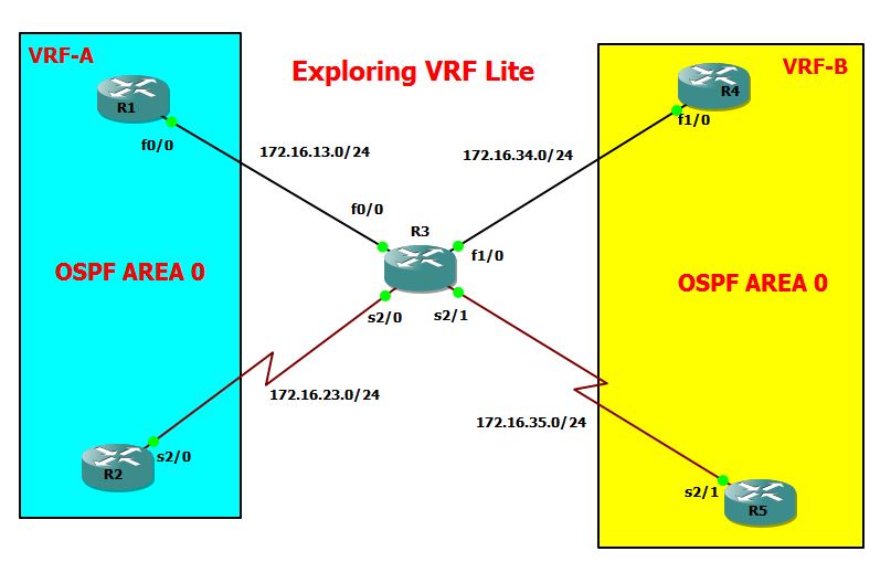
Let’s configure VRF-A:
Below are my approach for the configurations..
1. Enable OSPF on R1 & R2..
2. Create the VRF instance ( VRF-A)
3. Set up VRF forwarding on ISP interface that are connected to VRF-A customers..
4. Configure OSPF in ISP with the VRF command..
Configurations:
R1#sh run | sec ospf
router ospf 1
network 1.1.1.1 0.0.0.0 area 0
network 172.16.13.0 0.0.0.255 area 0
R2#sh run | sec ospf
router ospf 1
network 2.2.2.2 0.0.0.0 area 0
network 172.16.23.0 0.0.0.255 area 0
ISP#sh run | sec ospf
router ospf 1 vrf VRF-A
network 172.16.13.0 0.0.0.255 area 0
network 172.16.23.0 0.0.0.255 area 0
ISP#show ip ospf neighbor
Neighbor ID Pri State Dead Time Address Interface
1.1.1.1 1 FULL/DR 00:00:36 172.16.13.1 FastEthernet0/0
172.16.23.2 0 FULL/ – 00:00:32 172.16.23.2 Serial2/0
Let’s check the OSPF routes on ISP router…
ISP#show ip route vrf VRF-A ospf
Routing Table: VRF-A
Codes: L – local, C – connected, S – static, R – RIP, M – mobile, B – BGP
D – EIGRP, EX – EIGRP external, O – OSPF, IA – OSPF inter area
N1 – OSPF NSSA external type 1, N2 – OSPF NSSA external type 2
E1 – OSPF external type 1, E2 – OSPF external type 2
i – IS-IS, su – IS-IS summary, L1 – IS-IS level-1, L2 – IS-IS level-2
ia – IS-IS inter area, * – candidate default, U – per-user static route
o – ODR, P – periodic downloaded static route, H – NHRP, l – LISP
+ – replicated route, % – next hop override
Gateway of last resort is not set
1.0.0.0/32 is subnetted, 1 subnets
O 1.1.1.1 [110/2] via 172.16.13.1, 00:28:01, FastEthernet0/0
2.0.0.0/32 is subnetted, 1 subnets
O 2.2.2.2 [110/65] via 172.16.23.2, 01:13:52, Serial2/0
ISP#
Let’s check the connectivity from R1 to R2..
R1#ping 2.2.2.2 source 1.1.1.1
Type escape sequence to abort.
Sending 5, 100-byte ICMP Echos to 2.2.2.2, timeout is 2 seconds:
Packet sent with a source address of 1.1.1.1
!!!!!
Success rate is 100 percent (5/5), round-trip min/avg/max = 56/71/84 ms
R1#
We can also do that from the ISP router with the following command:
ISP#ping vrf VRF-A 2.2.2.2
Type escape sequence to abort.
Sending 5, 100-byte ICMP Echos to 2.2.2.2, timeout is 2 seconds:
!!!!!
Success rate is 100 percent (5/5), round-trip min/avg/max = 52/56/60 ms
ISP#ping vrf VRF-A 1.1.1.1
Type escape sequence to abort.
Sending 5, 100-byte ICMP Echos to 1.1.1.1, timeout is 2 seconds:
!!!!!
Success rate is 100 percent (5/5), round-trip min/avg/max = 56/60/72 ms
NOW, let’s configure VRF-B…
R4#sh run | sec ospf
router ospf 1
network 4.4.4.4 0.0.0.0 area 0
network 172.16.34.0 0.0.0.255 area 0
R5#sh run | sec ospf
router ospf 1
network 5.5.5.5 0.0.0.0 area 0
network 172.16.35.0 0.0.0.255 area 0
ISP#sh run | sec ospf
router ospf 2 vrf VRF-B
network 172.16.34.0 0.0.0.255 area 0
network 172.16.35.0 0.0.0.255 area 0
Let’s check the OSPF neighbors:
ISP#show ip ospf neighbor
Neighbor ID Pri State Dead Time Address Interface
5.5.5.5 0 FULL/ – 00:00:39 172.16.35.5 Serial2/1
172.16.34.4 1 FULL/DR 00:00:28 172.16.34.4 FastEthernet1/0
1.1.1.1 1 FULL/DR 00:00:34 172.16.13.1 FastEthernet0/0
172.16.23.2 0 FULL/ – 00:00:29 172.16.23.2 Serial2/0
ISP#
So what does the ISP tells about it’s VRF-B routing table…So ISP have both R4 and R5 loopback address…
ISP#show ip route vrf VRF-B ospf
Routing Table: VRF-B
Codes: L – local, C – connected, S – static, R – RIP, M – mobile, B – BGP
D – EIGRP, EX – EIGRP external, O – OSPF, IA – OSPF inter area
N1 – OSPF NSSA external type 1, N2 – OSPF NSSA external type 2
E1 – OSPF external type 1, E2 – OSPF external type 2
i – IS-IS, su – IS-IS summary, L1 – IS-IS level-1, L2 – IS-IS level-2
ia – IS-IS inter area, * – candidate default, U – per-user static route
o – ODR, P – periodic downloaded static route, H – NHRP, l – LISP
+ – replicated route, % – next hop override
Gateway of last resort is not set
4.0.0.0/32 is subnetted, 1 subnets
O 4.4.4.4 [110/2] via 172.16.34.4, 00:18:04, FastEthernet1/0
5.0.0.0/32 is subnetted, 1 subnets
O 5.5.5.5 [110/65] via 172.16.35.5, 00:17:54, Serial2/1
But as we can see from the results below, the global routing table does not show any OSPF routes..
ISP#show ip route ospf
Codes: L – local, C – connected, S – static, R – RIP, M – mobile, B – BGP
D – EIGRP, EX – EIGRP external, O – OSPF, IA – OSPF inter area
N1 – OSPF NSSA external type 1, N2 – OSPF NSSA external type 2
E1 – OSPF external type 1, E2 – OSPF external type 2
i – IS-IS, su – IS-IS summary, L1 – IS-IS level-1, L2 – IS-IS level-2
ia – IS-IS inter area, * – candidate default, U – per-user static route
o – ODR, P – periodic downloaded static route, H – NHRP, l – LISP
+ – replicated route, % – next hop override
Gateway of last resort is not set
ISP#
Let’s check the connectivity between R4 and R5…
R4#ping 5.5.5.5 source 4.4.4.4
Type escape sequence to abort.
Sending 5, 100-byte ICMP Echos to 5.5.5.5, timeout is 2 seconds:
Packet sent with a source address of 4.4.4.4
!!!!!
Success rate is 100 percent (5/5), round-trip min/avg/max = 60/79/88 ms
R4#
We can also test the connections from ISP router,
ISP#ping vrf VRF-B 4.4.4.4
Type escape sequence to abort.
Sending 5, 100-byte ICMP Echos to 4.4.4.4, timeout is 2 seconds:
!!!!!
Success rate is 100 percent (5/5), round-trip min/avg/max = 52/55/60 ms
ISP#ping vrf VRF-B 5.5.5.5
Type escape sequence to abort.
Sending 5, 100-byte ICMP Echos to 5.5.5.5, timeout is 2 seconds:
!!!!!
Success rate is 100 percent (5/5), round-trip min/avg/max = 52/56/60 ms
ISP#
***************************END OF LAB***********************************
Enabling Label Distribution Protocol through OSPF
This is another series of my learning journey on MPLS…Main focus is to provide an alternative ways on how to enable MPLS using the LDP protocols through OSPF…This is an another method to enable LDP aside from configuring using “mpls ip” with all the participating interfaces in the Service Provider…Label Distribution Protocol is the industry standard protocol to run MPLS…Cisco’s proprietary protocol is known as TDP or Tag Distribution Protocol.
So here’s my topology for this laboratory…

So here’s my OSPF configurations:
R1#sh run | sec ospf
router ospf 1
network 1.1.1.1 0.0.0.0 area 0
network 172.16.12.0 0.0.0.255 area 0
R2#sh run | sec ospf
router ospf 1
network 2.2.2.2 0.0.0.0 area 0
network 172.16.12.0 0.0.0.255 area 0
network 172.16.23.0 0.0.0.255 area 0
R3#sh run | sec ospf
router ospf 1
network 3.3.3.3 0.0.0.0 area 0
network 172.16.23.0 0.0.0.255 area 0
Let’s check the OSPF neighbors from R2:
R2#show ip ospf neighbor
Neighbor ID Pri State Dead Time Address Interface
3.3.3.3 0 FULL/ – 00:00:34 172.16.23.3 Serial2/1
172.16.12.1 0 FULL/ – 00:00:30 172.16.12.1 Serial2/0
R2#
Now, let me enable LDP under OSPF process using the command “mpls ldp autoconfig”:
R1(config)#router ospf 1
R1(config-router)#mpls ldp ?
autoconfig Configure LDP automatic configuration
sync Configure LDP-IGP Synchronization
R1(config-router)#mpls ldp autoconfig
R2(config-if)#router ospf 1
R2(config-router)#mpls ldp autoconfig
R3(config)#router ospf 1
R3(config-router)#mpls ldp autoconfig
Now, I can see that the LDP neighbors were UP..
R1(config-router)#
*Oct 18 17:13:39.647: %LDP-5-NBRCHG: LDP Neighbor 2.2.2.2:0 (1) is UP
R1(config-router)#^Z
R2(config-router)#
*Oct 18 17:13:51.991: %LDP-5-NBRCHG: LDP Neighbor 3.3.3.3:0 (2) is UP
R3(config-router)#
*Oct 18 17:13:50.931: %LDP-5-NBRCHG: LDP Neighbor 2.2.2.2:0 (1) is UP
R3(config-router)#^Z
One way to check whether the LDP is enabled on the interface is using the command “show mpls interface”..
R1#show mpls interfaces
Interface IP Tunnel BGP Static Operational
Serial2/0 Yes (ldp) No No No Yes
R1#
R2#show mpls interfaces
Interface IP Tunnel BGP Static Operational
Serial2/0 Yes (ldp) No No No Yes
Serial2/1 Yes (ldp) No No No Yes
R2#
R3#show mpls interfaces
Interface IP Tunnel BGP Static Operational
Serial2/1 Yes (ldp) No No No Yes
R3#
Let me LDP neighbor status from R2 using the command “show mpls ldp neighbor”
R2#show mpls ldp neighbor
Peer LDP Ident: 1.1.1.1:0; Local LDP Ident 2.2.2.2:0
TCP connection: 1.1.1.1.646 – 2.2.2.2.26066
State: Oper; Msgs sent/rcvd: 17/17; Downstream
Up time: 00:08:00
LDP discovery sources:
Serial2/0, Src IP addr: 172.16.12.1
Addresses bound to peer LDP Ident:
172.16.12.1 1.1.1.1
Peer LDP Ident: 3.3.3.3:0; Local LDP Ident 2.2.2.2:0
TCP connection: 3.3.3.3.28075 – 2.2.2.2.646
State: Oper; Msgs sent/rcvd: 17/16; Downstream
Up time: 00:07:48
LDP discovery sources:
Serial2/1, Src IP addr: 172.16.23.3
Addresses bound to peer LDP Ident:
172.16.23.3 3.3.3.3
The results shows that R2 has LDP peers to both 1.1.1.1 and 3.3.3.3 with the Peer LDP Identifier…
‘Now, let’s check the FIB Table ( Data Plane) and RIB Table (Control Plane) first”on R1…
FIB table —> This can be check with the “show ip cef”command:
R1#show ip cef 2.2.2.2
2.2.2.2/32
nexthop 172.16.12.2 Serial2/0
R1#show ip cef 3.3.3.3
3.3.3.3/32
nexthop 172.16.12.2 Serial2/0 label 17
RIB Table —> This can be checked with the command “show ip route
R1#show ip route 2.2.2.2
Routing entry for 2.2.2.2/32
Known via “ospf 1”, distance 110, metric 65, type intra area
Last update from 172.16.12.2 on Serial2/0, 00:14:20 ago
Routing Descriptor Blocks:
* 172.16.12.2, from 172.16.23.2, 00:14:20 ago, via Serial2/0
Route metric is 65, traffic share count is 1
R1#show ip route 3.3.3.3
Routing entry for 3.3.3.3/32
Known via “ospf 1”, distance 110, metric 129, type intra area
Last update from 172.16.12.2 on Serial2/0, 00:13:45 ago
Routing Descriptor Blocks:
* 172.16.12.2, from 3.3.3.3, 00:13:45 ago, via Serial2/0
Route metric is 129, traffic share count is 1
Now, since LDP was enable, we can check the LIB and LFIB table….
Let’s check this on R1…..
LIB Table –> we can check this with the command “show mpls ldp bindings
R1#show mpls ldp bindings
lib entry: 1.1.1.0/24, rev 2
local binding: label: imp-null
lib entry: 1.1.1.1/32, rev 11
remote binding: lsr: 2.2.2.2:0, label: 16
lib entry: 2.2.2.0/24, rev 12
remote binding: lsr: 2.2.2.2:0, label: imp-null
lib entry: 2.2.2.2/32, rev 4
local binding: label: 16
lib entry: 3.3.3.3/32, rev 6
local binding: label: 17
remote binding: lsr: 2.2.2.2:0, label: 17
lib entry: 172.16.12.0/24, rev 8
local binding: label: imp-null
remote binding: lsr: 2.2.2.2:0, label: imp-null
lib entry: 172.16.23.0/24, rev 10
local binding: label: 18
remote binding: lsr: 2.2.2.2:0, label: imp-null
Note: We can see that the Label starts at 16 and increments by 1…There were few Label that have value of IMP-NULL or Implicit Null..Another value for this is EXP-Null…
Let me check the LFIB ( Label Forwarding Information Based):
R1#show mpls forwarding-table
Local Outgoing Prefix Bytes Label Outgoing Next Hop
Label Label or Tunnel Id Switched interface
16 No Label 2.2.2.2/32 0 Se2/0 point2point
17 17 3.3.3.3/32 0 Se2/0 point2point
18 Pop Label 172.16.23.0/24 0 Se2/0 point2point
R1#
Now, let me try to change the Label numbers on the three routers…
R1:
mpls label range 100 200
R2:
mpls label range 200 300
R3:
mpls label range 300 400
I have to restart the router to have the new Label Take effect:
R1#show mpls forwarding-table
Local Outgoing Prefix Bytes Label Outgoing Next Hop
Label Label or Tunnel Id Switched interface
100 200 3.3.3.3/32 0 Se2/0 point2point
101 No Label 2.2.2.2/32 0 Se2/0 point2point
102 Pop Label 172.16.23.0/24 0 Se2/0 point2point
Let’s see what’s the Label of 3.3.3.3/32 in R2..`the local Label is 200 as this is the starting value of label range which I set up in R2…There’s no outgoing label in this case…
R2#show mpls forwarding-table
Local Outgoing Prefix Bytes Label Outgoing Next Hop
Label Label or Tunnel Id Switched interface
200 No Label 3.3.3.3/32 0 Se2/1 point2point
201 No Label 1.1.1.1/32 0 Se2/0 point2point
Summary:
1. Aside from configuring “mpls ip”under the participating interface to enable LDP, we can enable LDP using the commands “mpls ldp autoconfig”.
2. We can change the Labels value on each LSR with the command “mpls label range”.
*****************END OF LAB*****************************************
MPLS Labels Explained
I’m still excited as I’m writing this post about MPLS…Initially, the topics of MPLS is quite intimidating and seems quite difficult to understand…But with the aid of right tools, e.g. wireshark and RFC’s…learning should be fun….
On this post, I’m going into the details of the MPLS Labels… RFC 3032 provides a complete details of MPLS …MPLS labels has 4 components as shown below,

Generally, we have to take note that MPLS labels have 4 components …
1. Label Value – This 20-bit field carries the actual value of the Label.
2. Experimental – Which is a 3 bit field that is used for QoS…
3. Bottom of Stack (S)– this is used to informed if additional MPLS header is in the
queue. If the value of this is set to 1, this will be the final MPLS header but when this is
set 0, their is another MPLS header in stack..
4. TTL – This is similar to any TTL value which decrements by 1 everytime it passes a layer
3 devices.
To explore the MPLS labels, I will be using just a simple connections and will be using wireshark to capture the traffic…Below is my topology…

So here is my LDP configurations on both R1 and R2:
R1(config)#int s2/0
R1(config-if)#ip add 172.16.12.1 255.255.255.0
R1(config-if)#no shut
R1(config-if)#mpls ip
R2(config)#int s2/0
R2(config-if)#ip add 172.16.12.2 255.255.255.0
R2(config-if)#no shut
R2(config-if)#mpls ip
The moment that I have enabled LDP on both routers, LDP neighbors were formed as shown below,
R1(config-if)#
*Oct 18 12:16:28.919: %LDP-5-NBRCHG: LDP Neighbor 172.16.12.2:0 (1) is UP
R1(config-if)#
R2(config-if)#
*Oct 18 12:16:28.711: %LDP-5-NBRCHG: LDP Neighbor 172.16.12.1:0 (1) is UP
We can quickly checked this as well with the command ” show mpls ldp neighbor” :
R1#show mpls ldp neighbor
Peer LDP Ident: 2.2.2.2:0; Local LDP Ident 1.1.1.1:0
TCP connection: 2.2.2.2.37014 – 1.1.1.1.646
State: Oper; Msgs sent/rcvd: 21/20; Downstream
Up time: 00:13:18
LDP discovery sources:
Serial2/0, Src IP addr: 172.16.12.2
Addresses bound to peer LDP Ident:
172.16.12.2 2.2.2.2
Now, let’s capture the LDP sessions via wireshark…

**** As observed above, a Hello Message is exchange between R1 and R2
Taking a look at the IP Header, it shows that the Destination address is a multicast address 224.0.0.2 with Source and Destination Port set to 646…

Now, let’s take a look on the LDP protocol…

IMPORTANT:
1. We can see the important fields such as the LSR ID which is the Router ID…This should be the
highest loopback interface address on the router..
2. We can also see the Transport Address which is the same as the LSR ID and is used which is used
to established the TCP connection between the routers.
Now, let’s check the LDP neighbor status:
R1#show mpls ldp discovery
Local LDP Identifier:
1.1.1.1:0
Discovery Sources:
Interfaces:
Serial2/0 (ldp): xmit/recv
LDP Id: 2.2.2.2:0; no route <<< It shows that there’s no route…
R2#show mpls ldp discovery
Local LDP Identifier:
2.2.2.2:0
Discovery Sources:
Interfaces:
Serial2/0 (ldp): xmit/recv
LDP Id: 1.1.1.1:0; no route <<< It shows that there’s no route..
In this case, I still need to built the connectivity between loopbacks..I never set up static route or dynamic routes..In my example, I will prefer to used BGP to enable connectivity between the loopbacks..As I’m running IBGP, I’m setting up IGP using OSPF and peer the BGP with the loopback interface..Then to ensure connectivity, I have to advertise the loopbacks into BGP…
( Note: Even just configuring OSPF between this two routers will keep the LDP TCP connection works) … Just trying to simulate environment within the ISP setup with simple IBGP..
R1#sh run | sec ospf
router ospf 1
network 1.1.1.1 0.0.0.0 area 0
network 172.16.12.0 0.0.0.255 area 0
R1#sh run | sec bgp
router bgp 65000
bgp log-neighbor-changes
network 1.1.1.0 mask 255.255.255.0
neighbor 2.2.2.2 remote-as 65000
neighbor 2.2.2.2 update-source Loopback1
neighbor 2.2.2.2 next-hop-self
R2#sh run | sec ospf
router ospf 1
network 2.2.2.2 0.0.0.0 area 0
network 172.16.12.0 0.0.0.255 area 0
R2#sh run | sec bgp
router bgp 65000
bgp log-neighbor-changes
network 2.2.2.0 mask 255.255.255.0
neighbor 1.1.1.1 remote-as 65000
neighbor 1.1.1.1 update-source Loopback2
neighbor 1.1.1.1 next-hop-self
Checking the status of both routers IGP and BGP…
R1#show ip ospf neighbor
Neighbor ID Pri State Dead Time Address Interface
2.2.2.2 0 FULL/ – 00:00:39 172.16.12.2 Serial2/0
R1#show ip bgp summary
!
Neighbor V AS MsgRcvd MsgSent TblVer InQ OutQ Up/Down State/PfxRcd
2.2.2.2 4 65000 8 8 3 0 0 00:03:24 1
R1#
Now, going back and checking the LDP status discovery,
R1#show mpls ldp discovery
Local LDP Identifier:
1.1.1.1:0
Discovery Sources:
Interfaces:
Serial2/0 (ldp): xmit/recv
LDP Id: 2.2.2.2:0
R2#show mpls ldp discovery
Local LDP Identifier:
2.2.2.2:0
Discovery Sources:
Interfaces:
Serial2/0 (ldp): xmit/recv
LDP Id: 1.1.1.1:0
I should be able to see as well the LDP forwarding tables ( or the so called Label Forwarding Information Based – LFID)…
R1#show mpls forwarding-table
Local Outgoing Prefix Bytes Label Outgoing Next Hop
Label Label or Tunnel Id Switched interface
16 No Label 2.2.2.2/32 0 Se2/0 point2point
IMPORTANT:
1. It should be notice that LFIB is analogous the the CEF Table which is stored on a part of router’s memory called the Forwarding Information Based (FIB)…
2. As we know the routing table of any dynamic or static routing protocols is stored on the Routing Information Based ( RIB)…With LDP, this is called LIB or Label Information Based…This is where all the Prefix or Tunnel ID’s have automatically generated with a Local Label which is keep in the LIB…It is important to note that all the prefix on the RIB have been automatically assigned a local Label by each routers which are stored in the LIB…
3. Another important thing to note is that both the RIB and LIB are part of the routers Control Plane while the FIB and the LFIB are part of the Data Plane…
So what is Contol Plane and Data Plane?
Just imagine that Control Plane is responsible for building the routing table, gathering the ARP and MAC address entries while Data Plane is responsible for the actual forwarding of packets..
So in comparisons, here are the mappings of the important tables for Dynamic protocols and LDP:
BGP/OSPF LDP
RIB LIB
FIB LFIB
RIB – Routing Information Based
FIB – Forwarding Information Based
LIB – Label Information Based
LFID – Label Forwarding Information Based
Now, let’s check the LIB of R1 using the command ” show mpls ldp bindings“
R1#show mpls ldp bindings
lib entry: 1.1.1.0/24, rev 2
local binding: label: imp-null
lib entry: 1.1.1.1/32, rev 8
remote binding: lsr: 2.2.2.2:0, label: 16
lib entry: 2.2.2.0/24, rev 7
remote binding: lsr: 2.2.2.2:0, label: imp-null
lib entry: 2.2.2.2/32, rev 6
local binding: label: 16
lib entry: 172.16.12.0/24, rev 4
local binding: label: imp-null
remote binding: lsr: 2.2.2.2:0, label: imp-null
So in summary, I have the following important concepts to understand with MPLS labels:
1. MPLS labels have 4 fields as follows:
Label Value – 20 bits
EXP – 3 bits
S Field or Bottom of Stack field with 1 bit
TTL field with 3 bits
2. To enabled LDP, we can use the command “mpls ip” under the participating LDP interface.
3. The RIB or Routing Information Based which keeps a copy of the routing tables of any IGP when LDP is enabled will be PUSH (attached with a label)…This prefix will be stored on LDP’s LIB or Label Information Based….
4. The actual switching of LIB’s are done by the LFIB or the Label Forwarding Information Based which is in data plane of the router…This is where the SWAP label is happening…
5. Below are summary of important show commands to check for the LDP status:
- show mpls ldp neighbor — used to check LDP neighbor status
- show mpls forwarding-table — this is used to check the LFIB
- show mpls ldp binding — this is used to check LIB
- show ip route – to check RIB
- show ip cef — to check FIB
**********************END OF LAB *********************************************
MPLS Explained
This post is still part of my learning journey towards my CCIE Routing and Switching…I will be going through a basic configurations of MPLS and dig deeper into how MPLS labels were switched between routers…MPLS is using LDP or Label Distribution Protocol which used a label to switched packets across Label Edge Routers and Label Switch Routers…..
So what are the components of a MPLS?
CE: Customer Edge Router
PE: Provider Edge Router also known as LER or Label Edge Router
P: Label Switch Routers (LSR) or Transit Router..
Moreover, there are three actions that happens as labels are switched between the PE to P routers:
Label Push: This means that labels are being added to a prefix
Label Swap: This means that labels were swap or replace with another labels as it passes from PE to
P
Label Pop: This means that the label are being remove. This happens before the PE router on the
destinations side.
I will be using the diagram below to show how MPLS works:

CE1 Configurations:
|
CE1#sh run | sec bgp
router bgp 1000 bgp log-neighbor-changes network 1.1.1.0 mask 255.255.255.0 neighbor 172.16.12.2 remote-as 65512 |
CE2 Configurations:
|
CE2#sh run | sec bgp
router bgp 5000 bgp log-neighbor-changes network 5.5.5.0 mask 255.255.255.0 neighbor 172.16.45.4 remote-as 65512 |
PE1 Configurations
|
PE1#sh run | sec ospf
router ospf 1 network 2.2.2.2 0.0.0.0 area 0 network 172.16.23.0 0.0.0.255 area 0 PE1#sh run | sec bgp
router bgp 65512 bgp log-neighbor-changes neighbor 4.4.4.4 remote-as 65512 neighbor 4.4.4.4 update-source Loopback2 neighbor 4.4.4.4 next-hop-self neighbor 172.16.12.1 remote-as 1000 |
ISP or Provider Router Configuration
|
ISP#sh run | sec ospf
router ospf 1 network 3.3.3.3 0.0.0.0 area 0 network 172.16.23.0 0.0.0.255 area 0 network 172.16.34.0 0.0.0.255 area 0 |
PE2 Configurations:
| PE2#sh run | sec ospf router ospf 1 network 4.4.4.4 0.0.0.0 area 0 network 172.16.34.0 0.0.0.255 area 0 PE2#sh run | sec bgp |
So here’s the BGP Status of each of the routers…
CE1#sh ip bgp summary
!
Neighbor V AS MsgRcvd MsgSent TblVer InQ OutQ Up/Down State/PfxRcd
172.16.12.2 4 65512 81 78 3 0 0 01:06:58 1
CE1#
PE1#show ip bgp summary
!
Neighbor V AS MsgRcvd MsgSent TblVer InQ OutQ Up/Down State/PfxRcd
4.4.4.4 4 65512 129 124 9 0 0 01:48:25 1
172.16.12.1 4 1000 78 82 9 0 0 01:10:36 1
PE1#
So for ISP, I never set up BGP on this router but rather, it’s running an IGP between PE1 and PE2..
ISP#show ip bgp summary
% BGP not active
PE2#show ip bgp summary
!
Neighbor V AS MsgRcvd MsgSent TblVer InQ OutQ Up/Down State/PfxRcd
2.2.2.2 4 65512 126 130 9 0 0 01:49:34 1
172.16.45.5 4 5000 80 82 9 0 0 01:11:32 1
PE2#
CE2#sh ip bgp summary
!
Neighbor V AS MsgRcvd MsgSent TblVer InQ OutQ Up/Down State/PfxRcd
172.16.45.4 4 65512 73 71 3 0 0 01:00:19 1
Now, let me show how to enable Label Distribution Protocol on the PE1, ISP or P and PE2 router…
|
PE1#sh run int s2/1
Building configuration… Current configuration : 98 bytes ISP#sh run int s2/1 Building configuration… Current configuration : 89 bytes mpls ip
serial restart-delay 0 end ISP#sh run int s2/2 Current configuration : 98 bytes PE2#sh run int s2/2
Building configuration… Current configuration : 98 bytes |
So the moment that I have enabled the Label Distribution Protocol using the command “mpls ip”
under the interface between PE1 to P/ISP to PE2.., the LDP neighbors were formed…
|
PE1#
*Oct 18 00:34:54.114: %LDP-5-NBRCHG: LDP Neighbor 3.3.3.3:0 (1) is UP ISP#
*Oct 18 00:35:53.846: %LDP-5-NBRCHG: LDP Neighbor 2.2.2.2:0 (2) is UP ISP(config-if)#
*Oct 18 00:15:40.854: %LDP-5-NBRCHG: LDP Neighbor 4.4.4.4:0 (1) is UP PE2(config-if)# *Oct 18 00:13:42.166: %LDP-5-NBRCHG: LDP Neighbor 3.3.3.3:0 (1) is UP |
As we can see from my configs, I have advertised 1.1.1.1/24 in CE1 and 5.5.5.5/24 in CE2…This is
something we can check on the PE1, P and PE2…
Ping from CE1 to CE2 loopback and vice-versa is working fine…
|
CE1#ping 5.5.5.5 source 1.1.1.1
Type escape sequence to abort. Sending 5, 100-byte ICMP Echos to 5.5.5.5, timeout is 2 seconds: Packet sent with a source address of 1.1.1.1 !!!!! Success rate is 100 percent (5/5), round-trip min/avg/max = 72/78/84 ms CE1# CE2#ping 1.1.1.1 source 5.5.5.5
Type escape sequence to abort. Sending 5, 100-byte ICMP Echos to 1.1.1.1, timeout is 2 seconds: Packet sent with a source address of 5.5.5.5 !!!!! Success rate is 100 percent (5/5), round-trip min/avg/max = 112/136/152 ms CE2# |
Now, let’s check how the traffic from R1 reached R5..
From CE1 BGP database, in order to reach 5.5.5.5, it has to go through PE1..
|
CE1#show ip bgp
BGP table version is 3, local router ID is 1.1.1.1 Status codes: s suppressed, d damped, h history, * valid, > best, i – internal, r RIB-failure, S Stale, m multipath, b backup-path, f RT-Filter, x best-external, a additional-path, c RIB-compressed, Origin codes: i – IGP, e – EGP, ? – incomplete RPKI validation codes: V valid, I invalid, N Not found Network Next Hop Metric LocPrf Weight Path CE1#show ip route bgp
Codes: L – local, C – connected, S – static, R – RIP, M – mobile, B – BGP D – EIGRP, EX – EIGRP external, O – OSPF, IA – OSPF inter area N1 – OSPF NSSA external type 1, N2 – OSPF NSSA external type 2 E1 – OSPF external type 1, E2 – OSPF external type 2 i – IS-IS, su – IS-IS summary, L1 – IS-IS level-1, L2 – IS-IS level-2 ia – IS-IS inter area, * – candidate default, U – per-user static route o – ODR, P – periodic downloaded static route, H – NHRP, l – LISP + – replicated route, % – next hop override Gateway of last resort is not set 5.0.0.0/24 is subnetted, 1 subnets |
Now, let’s check PE1 …As observed, in order to reach 5.5.5.5, it has to go through with PE2…
|
PE1#show ip route 5.5.5.5
Routing entry for 5.5.5.0/24 Known via “bgp 65512“, distance 200, metric 0 Tag 5000, type internal Last update from 4.4.4.4 00:13:17 ago Routing Descriptor Blocks: * 4.4.4.4, from 4.4.4.4, 00:13:17 ago Route metric is 0, traffic share count is 1 AS Hops 1 Route tag 5000 MPLS label: none |
But since I have enabled LDP, let’s check the MPLS forwarding table instead on PE1 ( This is
analogous to BGP database table) with the command “show mpls forwarding-table”
|
PE1#show mpls forwarding-table
Local Outgoing Prefix Bytes Label Outgoing Next Hop Label Label or Tunnel Id Switched interface 16 No Label 3.3.3.3/32 0 Se2/1 point2point 17 17 4.4.4.4/32 0 Se2/1 point2point 18 Pop Label 172.16.34.0/24 0 Se2/1 point2point PE1# |
|
So what can we see from the output of the MPLS forwarding table above…
1. LDP have assigned a Local Label and Outgoing Label to a Prefix or Tunnel ID…
2. The Label always start with a value of 16…
3. It does shows a Pop Label is having the Prefix 172.16.34.0/24…as we know this is the prefix for the
link between P router (ISP) and the PE2..
4. We can see the Outgoing Label which is “Pop Label”… This means that PE1 will removed the label
before passing the traffic to CE1…
IMPORTANT: There’s a concept known as PHP or Penultimate Hop Popping in which the label
were removed (POP) before passing the traffic to the destination PE so avoid lookups
of Label on the that router..
|
There are three types of packet switching in which by default Cisco routers are using IP CEF. This
is used by LDP to switched packets. The other two types include process switching and route
caching or fast forwarding.
Now, let me check the specific CEF table towards the destination loopback of R5 using the
command “show ip cef”
PE1#show ip cef 5.5.5.5
5.5.5.0/24
nexthop 172.16.23.3 Serial2/1 label 17
PE1#
So what does the output of “show ip cef 5.5.5.5” on PE1 indicates…
1. It shows that the next hop address is the P or ISP router..
2. It shows that the interface it will used to pass the label is Serial 2/1
3. Finally, it shows that local label is 17..
But what does P or ISP router or Transit router is telling us? So it shows below that there is no route towards 5.5.5.5..This is true because, I never set up IBGP between ISP and PE1 and PE2…
ISP#show ip cef 5.5.5.5
0.0.0.0/0
no route
IMPORTANT: Take note that labels are only local to the Router…When it pass the label to the next router, it will be change (LABEL SWAP) by the router and stores it in its LDP table…The Label might be the same number though as the labels by default always starts with 16 and increments by 1…
Now, let me check the P or ISP router Forwarding Table ( LDP Table):
ISP#show mpls forwarding-table
Local Outgoing Prefix Bytes Label Outgoing Next Hop
Label Label or Tunnel Id Switched interface
16 No Label 2.2.2.2/32 9236 Se2/1 point2point
17 No Label 4.4.4.4/32 7276 Se2/2 point2point
So here is what happens:
1. When ISP received a label tag with 17, then it has to forward that to 4.4.4.4 (PE2)..
2. Similarly, when it received a label with tag of 16, it has to forward to 2.2.2.2 (PE1)..
As expected, there should no CEF table for 5.5.5.5 from the P router..
ISP#show ip cef 5.5.5.5
0.0.0.0/0
no route
Now, let’s take a look on the LDP forwarding table of PE2..
PE2#show mpls forwarding-table
Local Outgoing Prefix Bytes Label Outgoing Next Hop
Label Label or Tunnel Id Switched interface
16 16 2.2.2.2/32 0 Se2/2 point2point
17 No Label 3.3.3.3/32 0 Se2/2 point2point
18 Pop Label 172.16.23.0/24 0 Se2/2 point2point
As observed, the Outgoing Label Tag as Pop Label for the prefix 172.16.23.0/24…
By this time, let’s check the CEF table on PE2..
PE2#show ip cef 5.5.5.5
5.5.5.0/24
nexthop 172.16.45.5 Serial2/0
PE2#
>>> So the above results is showing that the label were already removed. As we have seen on the previous configurations of the LDP, it’s only enabled on Serial 2/2 of the PE2 but not on the interface facing CE2…
On the other hand, the IP CEF results towards 1.1.1.1 shows that it’s label has a value of 16 and the next hop is the P or ISP router..
PE2#show ip cef 1.1.1.1
1.1.1.0/24
nexthop 172.16.34.3 Serial2/2 label 16
Finally, we can check from PE2 that 5.5.5.5 is advertise via BGP…
PE2#show ip route bgp
!
Gateway of last resort is not set
1.0.0.0/24 is subnetted, 1 subnets
B 1.1.1.0 [200/0] via 2.2.2.2, 01:47:46
5.0.0.0/24 is subnetted, 1 subnets
B 5.5.5.0 [20/0] via 172.16.45.5, 01:47:49
In summary, here are the important terms/configurations to set up MPLS:
A. MPLS device components:
– CE Router
– PE Router or Label Edge Router (LER)
– P or ISP router also known as Label Switch Router (LSR) or Transit router…
B. Label switching happens with three important steps:
– Label Push
– Label Swap
– Label Pop
C. LDP or Label Distribution Protocol is the industry standard to enable MPLS…Cisco’s
proprietary protocol which performs the same functionality is called TDP or Tag Distribution
Protocol..
Now, in order to enable LDP neighbors, we can used the following two commands:
1. On all participating interface to established LDP neighbors, we can configured
mpls ip
2. Alternative options is to enable LDP is to apply ” mpls ldp autoconfig “ under any IGP routing
protocol such as OSPF..
D. To verify the LDP Table or MPLS Forwarding table, we can used the command:
show mpls forwarding-table
E. To verify specific label on a destination address, we can used the command below:
show ip cef “x.x.x.x”
**************************END OF LAB***************************************
GRE Tunelling Explored
On this post, I will be exploring a concept called GRE Tunneling…GRE tunneling is a tunneling mechanism which uses IP as the transport protocol that carries several passenger protocols. In the nutshell, in order to formed GRE tunnels, a virtual point-to-point links with two endpoints known as Tunnel source and Tunnel destinations should be set up.
The best analogy for GRE tunneling will be a bus with passengers traveling in a highway…The bus passengers or people inside the bus is similar to a passenger protocol, e.g. TCP or UDP while the bus is called the transport protocol, e.g. IP.
Below will be my laboratory topology to show how GRE is configured…

EBGP Configurations:
|
R1#sh run | sec bgp
router bgp 1000 bgp log-neighbor-changes network 1.1.1.0 mask 255.255.255.0 neighbor 172.16.12.2 remote-as 65512 |
EBGP and IBGP Configurations:
|
R2#sh run | sec bgp
router bgp 65512 bgp log-neighbor-changes neighbor 172.16.12.1 remote-as 1000 neighbor 172.16.23.3 remote-as 65512 |
IBGP Configurations:
|
R3#sh run | sec bgp
router bgp 65512 bgp log-neighbor-changes neighbor 172.16.23.2 remote-as 65512 neighbor 172.16.34.4 remote-as 65512 |
EBGP and IBGP Configurations:
|
R4#sh run | sec bgp
router bgp 65512 bgp log-neighbor-changes neighbor 172.16.34.3 remote-as 65512 neighbor 172.16.45.5 remote-as 5000 |
EBGP Configuration:
|
R5#sh run | sec bgp
router bgp 5000 bgp log-neighbor-changes network 5.5.5.0 mask 255.255.255.0 neighbor 172.16.45.4 remote-as 65512 |
Let’s check the BGP Neighbors:
|
R1#sh ip bgp summary
BGP router identifier 1.1.1.1, local AS number 1000 BGP table version is 3, main routing table version 3 2 network entries using 288 bytes of memory 2 path entries using 160 bytes of memory 2/2 BGP path/bestpath attribute entries using 272 bytes of memory 1 BGP AS-PATH entries using 24 bytes of memory 0 BGP route-map cache entries using 0 bytes of memory 0 BGP filter-list cache entries using 0 bytes of memory BGP using 744 total bytes of memory BGP activity 2/0 prefixes, 2/0 paths, scan interval 60 secs Neighbor V AS MsgRcvd MsgSent TblVer InQ OutQ Up/Down State/PfxRcd R2#sh ip bgp summary
BGP router identifier 2.2.2.2, local AS number 65512 BGP table version is 3, main routing table version 3 2 network entries using 288 bytes of memory 2 path entries using 160 bytes of memory 2/2 BGP path/bestpath attribute entries using 272 bytes of memory 2 BGP AS-PATH entries using 48 bytes of memory 0 BGP route-map cache entries using 0 bytes of memory 0 BGP filter-list cache entries using 0 bytes of memory BGP using 768 total bytes of memory BGP activity 2/0 prefixes, 2/0 paths, scan interval 60 secs Neighbor V AS MsgRcvd MsgSent TblVer InQ OutQ Up/Down State/PfxRcd R3#sh ip bgp summary
BGP router identifier 3.3.3.3, local AS number 65512 BGP table version is 1, main routing table version 1 2 network entries using 288 bytes of memory 2 path entries using 160 bytes of memory 2/0 BGP path/bestpath attribute entries using 272 bytes of memory 2 BGP AS-PATH entries using 48 bytes of memory 0 BGP route-map cache entries using 0 bytes of memory 0 BGP filter-list cache entries using 0 bytes of memory BGP using 768 total bytes of memory BGP activity 2/0 prefixes, 2/0 paths, scan interval 60 secs Neighbor V AS MsgRcvd MsgSent TblVer InQ OutQ Up/Down State/PfxRcd R4#sh ip bgp summary
BGP router identifier 4.4.4.4, local AS number 65512 BGP table version is 3, main routing table version 3 2 network entries using 288 bytes of memory 2 path entries using 160 bytes of memory 2/2 BGP path/bestpath attribute entries using 272 bytes of memory 2 BGP AS-PATH entries using 48 bytes of memory 0 BGP route-map cache entries using 0 bytes of memory 0 BGP filter-list cache entries using 0 bytes of memory BGP using 768 total bytes of memory BGP activity 2/0 prefixes, 2/0 paths, scan interval 60 secs Neighbor V AS MsgRcvd MsgSent TblVer InQ OutQ Up/Down State/PfxRcd R5#sh ip bgp summary BGP router identifier 5.5.5.5, local AS number 5000 BGP table version is 3, main routing table version 3 2 network entries using 288 bytes of memory 2 path entries using 160 bytes of memory 2/2 BGP path/bestpath attribute entries using 272 bytes of memory 1 BGP AS-PATH entries using 24 bytes of memory 0 BGP route-map cache entries using 0 bytes of memory 0 BGP filter-list cache entries using 0 bytes of memory BGP using 744 total bytes of memory BGP activity 2/0 prefixes, 2/0 paths, scan interval 60 secs Neighbor V AS MsgRcvd MsgSent TblVer InQ OutQ Up/Down State/PfxRcd |
Since BGP Neighbors were formed, we can start creating the GRE Tunnel between R2 and R4…
|
R2#sh run int tunnel 0
Building configuration… Current configuration : 114 bytes R4#sh run int Tunnel 0
Building configuration… Current configuration : 114 bytes |
Let’s check the tunnel interface…
|
R2#show ip int brief
Interface IP-Address OK? Method Status Protocol FastEthernet0/0 unassigned YES unset administratively down down FastEthernet1/0 unassigned YES unset administratively down down FastEthernet1/1 unassigned YES unset administratively down down Serial2/0 172.16.12.2 YES manual up up Serial2/1 172.16.23.2 YES manual up up Serial2/2 unassigned YES unset administratively down down Serial2/3 unassigned YES unset administratively down down Loopback2 2.2.2.2 YES manual up up Tunnel0 172.16.24.2 YES manual up up R4#sh ip int brief Interface IP-Address OK? Method Status Protocol FastEthernet0/0 unassigned YES unset administratively down down FastEthernet1/0 unassigned YES unset administratively down down FastEthernet1/1 unassigned YES unset administratively down down Serial2/0 172.16.45.4 YES manual up up Serial2/1 unassigned YES unset administratively down down Serial2/2 172.16.34.4 YES manual up up Serial2/3 unassigned YES unset administratively down down Loopback4 4.4.4.4 YES manual up up Tunnel0 172.16.24.4 YES manual up up R4# |
To test the tunnel interface, I can traceroutes towards R5 loopback address from R1…As seen
below, the traffic did not go through R3 instead it does pass through the R2–>R4—> R5…
|
R1#traceroute 5.5.5.5 source 1.1.1.1
Type escape sequence to abort. Tracing the route to 5.5.5.5 VRF info: (vrf in name/id, vrf out name/id) 1 172.16.12.2 60 msec 80 msec 60 msec 2 172.16.24.4 100 msec 116 msec 100 msec 3 172.16.45.5 156 msec 128 msec 108 msec R1# |
Pinging R5 loopback sourcing R1 loopback address is also successful..
|
R1#ping 5.5.5.5 source 1.1.1.1
Type escape sequence to abort. Sending 5, 100-byte ICMP Echos to 5.5.5.5, timeout is 2 seconds: Packet sent with a source address of 1.1.1.1 !!!!! Success rate is 100 percent (5/5), round-trip min/avg/max = 148/174/200 ms R1# |
**********************************END OF LAB************************************
OSPF Hello Packets Deep Dive
This is a post which is part of my learning journey on OSPF…I will be going through the details of the different OSPF packet (Message) type and what are the components of each packet type…This will be best explained with the used of wireshark….To have an overview, the 5 OSPF Message Types includes the following:
1. Hello
2. DBD or Database Description
3. Link State Request
4. Link State Update
5. Link State Acknowledgment
Below will be my lab for this post…

OSPF Configurations:
|
R1#sh run | sec ospf
router ospf 1 network 1.1.1.1 0.0.0.0 area 1 network 192.168.12.0 0.0.0.255 area 0 R2#sh run | sec ospf
router ospf 1 network 2.2.2.2 0.0.0.0 area 2 network 192.168.12.0 0.0.0.255 area 0 |
The moment, we have enabled the network statement under the OSPF process on R1, the first
OSPF Hello Packet will be sent to the multicast address 224.0.0.5
|
|
The OSPF header would have the following:
1. OSPF Version
2. Message Type
3. Packet Length
4. OSPF Router
5. Area
6. Checksum
7. Authentication Type ( Plan Text, MD5 or No Authentications)
8. Authenticated Data
 |
Below are the information’s included on the Hello Packet. As we have notice the Hello Interval is
10 seconds and the Dead Intervals is 40 seconds ( 4 times the Hello Interval). Take note that the
following parameters have to be the same in order for the OSPF Neighbors will formed:
1. Network Mask
2. Hello Interval
3. Areas
4. Dead Interval
 |
The wireshark capture below shows the Hello Packets send to the multicast address 224.0.0.5 of
both R1 and R2 the moments, I have enabled the network command under the OSPF process.
|
|
Let’s take a look at R2 by this time…
|
|
|
As observed aboved R2 has the required parameters to formed the neigbor with R1.. This includes
– Same Network Mask as with R1
– Same Hello interval as with R1
– Same Area as R1
– Same Dead Interval as R1
|
Now, look at R2… It does shows the Active Neighbor which is R1.
 |
The next OSPF Message Type is the Database Description ( DBD)… This will only appear once the
OSPF neighbors were formed.
 |
DBD keeps all the LSA’s of all the routers within the area. As we only have one OSPF neighbor, on
my wireshark capture below, I only have a LSA Type 1 or Router LSA. Important thing to note with\ DBD message are as follows:
1. LSA Type
2. Link State ID
3. Advertising router
4. Sequence Number
5. Checksum
6. Length
|
|
The next OSPF Message is the LSR.. The picture below means that R1 is requesting for a newer
LSA from R2.
 |
In response to the LSR, R2 is sending an LSU…
 |
Finally, the last OSPF Message is the LS Acknowledgment or LS- Acknowledgment.
 |
Route Reflector
I’m going a bit further with my BGP study notes..On this post, I will be exploring Route Reflectors…Basically, for IBGP to completely work, we need to have a full mesh of IBGP peering to all routers within the Autonomous System…So if I have more routers, say, 10 routers on my AS, then I will need to have 15 MESH IBGP ( Formula is n(n-1)/2 ) connections which is very tedious to manage..
Important concepts for Route-Reflectors:
Peering to the following:
– IBGP Client Neighbor
– IBGP Non-Client Neighbor
– EBGP Neighbor
Two Important Fields to remember in Route Reflectors:
– Cluster List — this is the Route Reflector itself
– Originator ID — this is the Route Reflector Client
We can see this using the command “show ip bgp XXX” , XXX is the prefix that is advertise…
So here’s my laboratory set up..

Here are my router configurations based on my topology above:
|
R1#sh run | sec bgp
ipv6 multicast rpf use-bgp
router bgp 65000
bgp log-neighbor-changes
neighbor 172.16.12.2 remote-as 65000
neighbor 172.16.13.3 remote-as 65000
|
|
R2#sh run | sec bgp
ipv6 multicast rpf use-bgp
router bgp 65000
bgp log-neighbor-changes
network 22.22.22.0 mask 255.255.255.0
neighbor 172.16.12.1 remote-as 65000
neighbor 172.16.12.1 next-hop-self
neighbor 172.16.23.3 remote-as 65000
R2#
Key point:
1. R1 is a Route Reflector Client
2. I’m telling R1 that R2 is the next-hop router..
3. I have advertise the loopback interface address (22.22.22.22)
|
|
R3#sh run | sec bgp
ipv6 multicast rpf use-bgp
router bgp 65000
bgp log-neighbor-changes
network 172.16.12.0 mask 255.255.255.0
network 172.16.13.0 mask 255.255.255.0
network 172.16.23.0 mask 255.255.255.0
network 172.16.34.0 mask 255.255.255.0
neighbor 172.16.13.1 remote-as 65000
neighbor 172.16.13.1 route-reflector-client
neighbor 172.16.13.1 next-hop-self
neighbor 172.16.23.2 remote-as 65000
neighbor 172.16.23.2 route-reflector-client
neighbor 172.16.23.2 next-hop-self
neighbor 172.16.34.4 remote-as 65001
R3#
Key points here:
1. R3 is the Route Reflector
2. I have added R1 and R2 as a route reflector client
3. I’m telling R1 and R2 that R3 is the next hop for any prefix that R3 has learned from EBGP..
4. I need to advertise into BGP the subnets 172.16.12.0/24, 172.16.13.0/24, 172.16.23.0/24 and 172.16.34.0/24 so that R4 should know how to reach this subnets..
IMPORTANT… We can see a RIB on R3 for 172.16.34.0/24 as I have advertise it at the same time, it’s a direct link… I need to advertise it in R3 so that R1, R2 knows how to reach R4…
|
|
R4#sh run | sec bgp
ipv6 multicast rpf use-bgp
router bgp 65001
bgp log-neighbor-changes
network 4.4.4.0 mask 255.255.255.0
neighbor 172.16.34.3 remote-as 65000
R4#
>> This is just a normal EBGP to R3…
|
So let’s check the BGP database on each router…
|
R1#sh ip bgp
BGP table version is 15, local router ID is 1.1.1.1
Status codes: s suppressed, d damped, h history, * valid, > best, i – internal,
r RIB-failure, S Stale, m multipath, b backup-path, f RT-Filter,
x best-external, a additional-path, c RIB-compressed,
Origin codes: i – IGP, e – EGP, ? – incomplete
RPKI validation codes: V valid, I invalid, N Not found
Network Next Hop Metric LocPrf Weight Path
*>i 4.4.4.0/24 172.16.13.3 0 100 0 65001 i
* i 22.22.22.0/24 172.16.23.2 0 100 0 i
*>i 172.16.12.2 0 100 0 i
r>i 172.16.13.0/24 172.16.13.3 0 100 0 i
*>i 172.16.23.0/24 172.16.13.3 0 100 0 i
*>i 172.16.34.0/24 172.16.13.3 0 100 0 i
R1#
|
|
R2#show ip bgp
BGP table version is 6, local router ID is 22.22.22.22
Status codes: s suppressed, d damped, h history, * valid, > best, i – internal,
r RIB-failure, S Stale, m multipath, b backup-path, f RT-Filter,
x best-external, a additional-path, c RIB-compressed,
Origin codes: i – IGP, e – EGP, ? – incomplete
RPKI validation codes: V valid, I invalid, N Not found
Network Next Hop Metric LocPrf Weight Path
*>i 4.4.4.0/24 172.16.23.3 0 100 0 65001 i
*> 22.22.22.0/24 0.0.0.0 0 32768 i
*>i 172.16.13.0/24 172.16.23.3 0 100 0 i
r>i 172.16.23.0/24 172.16.23.3 0 100 0 i
*>i 172.16.34.0/24 172.16.23.3 0 100 0 i
R2#
|
|
R3#sh ip bgp
BGP table version is 8, local router ID is 33.33.33.33
Status codes: s suppressed, d damped, h history, * valid, > best, i – internal,
r RIB-failure, S Stale, m multipath, b backup-path, f RT-Filter,
x best-external, a additional-path, c RIB-compressed,
Origin codes: i – IGP, e – EGP, ? – incomplete
RPKI validation codes: V valid, I invalid, N Not found
Network Next Hop Metric LocPrf Weight Path
*> 4.4.4.0/24 172.16.34.4 0 0 65001 i
*>i 22.22.22.0/24 172.16.23.2 0 100 0 i
*> 172.16.13.0/24 0.0.0.0 0 32768 i
*> 172.16.23.0/24 0.0.0.0 0 32768 i
*> 172.16.34.0/24 0.0.0.0 0 32768 i
R3#
|
|
R4#show ip bgp
BGP table version is 14, local router ID is 4.4.4.4
Status codes: s suppressed, d damped, h history, * valid, > best, i – internal,
r RIB-failure, S Stale, m multipath, b backup-path, f RT-Filter,
x best-external, a additional-path, c RIB-compressed,
Origin codes: i – IGP, e – EGP, ? – incomplete
RPKI validation codes: V valid, I invalid, N Not found
Network Next Hop Metric LocPrf Weight Path
*> 4.4.4.0/24 0.0.0.0 0 32768 i
*> 22.22.22.0/24 172.16.34.3 0 65000 i
*> 172.16.13.0/24 172.16.34.3 0 0 65000 i
*> 172.16.23.0/24 172.16.34.3 0 0 65000 i
r> 172.16.34.0/24 172.16.34.3 0 0 65000 i
R4#
|
Let’ check the Routing table…
|
R1#show ip route bgp
Codes: L – local, C – connected, S – static, R – RIP, M – mobile, B – BGP
D – EIGRP, EX – EIGRP external, O – OSPF, IA – OSPF inter area
N1 – OSPF NSSA external type 1, N2 – OSPF NSSA external type 2
E1 – OSPF external type 1, E2 – OSPF external type 2
i – IS-IS, su – IS-IS summary, L1 – IS-IS level-1, L2 – IS-IS level-2
ia – IS-IS inter area, * – candidate default, U – per-user static route
o – ODR, P – periodic downloaded static route, H – NHRP, l – LISP
+ – replicated route, % – next hop override
Gateway of last resort is not set
4.0.0.0/24 is subnetted, 1 subnets
B 4.4.4.0 [200/0] via 172.16.13.3, 00:12:14
22.0.0.0/24 is subnetted, 1 subnets
B 22.22.22.0 [200/0] via 172.16.12.2, 00:22:42
172.16.0.0/16 is variably subnetted, 6 subnets, 2 masks
B 172.16.23.0/24 [200/0] via 172.16.13.3, 00:16:03
B 172.16.34.0/24 [200/0] via 172.16.13.3, 00:16:03
R1#
|
|
R2#show ip route bgp
Codes: L – local, C – connected, S – static, R – RIP, M – mobile, B – BGP
D – EIGRP, EX – EIGRP external, O – OSPF, IA – OSPF inter area
N1 – OSPF NSSA external type 1, N2 – OSPF NSSA external type 2
E1 – OSPF external type 1, E2 – OSPF external type 2
i – IS-IS, su – IS-IS summary, L1 – IS-IS level-1, L2 – IS-IS level-2
ia – IS-IS inter area, * – candidate default, U – per-user static route
o – ODR, P – periodic downloaded static route, H – NHRP, l – LISP
+ – replicated route, % – next hop override
Gateway of last resort is not set
4.0.0.0/24 is subnetted, 1 subnets
B 4.4.4.0 [200/0] via 172.16.23.3, 00:27:33
172.16.0.0/16 is variably subnetted, 6 subnets, 2 masks
B 172.16.13.0/24 [200/0] via 172.16.23.3, 00:12:33
B 172.16.34.0/24 [200/0] via 172.16.23.3, 00:27:33
R2#
|
|
R3#show ip route bgp
Codes: L – local, C – connected, S – static, R – RIP, M – mobile, B – BGP
D – EIGRP, EX – EIGRP external, O – OSPF, IA – OSPF inter area
N1 – OSPF NSSA external type 1, N2 – OSPF NSSA external type 2
E1 – OSPF external type 1, E2 – OSPF external type 2
i – IS-IS, su – IS-IS summary, L1 – IS-IS level-1, L2 – IS-IS level-2
ia – IS-IS inter area, * – candidate default, U – per-user static route
o – ODR, P – periodic downloaded static route, H – NHRP, l – LISP
+ – replicated route, % – next hop override
Gateway of last resort is not set
4.0.0.0/24 is subnetted, 1 subnets
B 4.4.4.0 [20/0] via 172.16.34.4, 00:32:08
22.0.0.0/24 is subnetted, 1 subnets
B 22.22.22.0 [200/0] via 172.16.23.2, 00:27:28
|
|
R4#show ip route bgp
Codes: L – local, C – connected, S – static, R – RIP, M – mobile, B – BGP
D – EIGRP, EX – EIGRP external, O – OSPF, IA – OSPF inter area
N1 – OSPF NSSA external type 1, N2 – OSPF NSSA external type 2
E1 – OSPF external type 1, E2 – OSPF external type 2
i – IS-IS, su – IS-IS summary, L1 – IS-IS level-1, L2 – IS-IS level-2
ia – IS-IS inter area, * – candidate default, U – per-user static route
o – ODR, P – periodic downloaded static route, H – NHRP, l – LISP
+ – replicated route, % – next hop override
Gateway of last resort is not set
22.0.0.0/24 is subnetted, 1 subnets
B 22.22.22.0 [20/0] via 172.16.34.3, 00:27:10
172.16.0.0/16 is variably subnetted, 4 subnets, 2 masks
B 172.16.13.0/24 [20/0] via 172.16.34.3, 00:13:05
B 172.16.23.0/24 [20/0] via 172.16.34.3, 00:31:14
R4#
|
Now, let me show the ROUTE REFLECTOR…from R3…I should be seeing the Prefix tag which is coming from RR Client…
|
R3#show ip bgp 22.22.22.22
BGP routing table entry for 22.22.22.0/24, version 7
Paths: (1 available, best #1, table default)
Advertised to update-groups:
9 10
Refresh Epoch 1
Local, (Received from a RR-client)
172.16.23.2 from 172.16.23.2 (22.22.22.22)
Origin IGP, metric 0, localpref 100, valid, internal, best
rx pathid: 0, tx pathid: 0x0
R3#
|
let’s check from an other Route Reflector Client..
|
R1#show ip bgp 22.22.22.22
BGP routing table entry for 22.22.22.0/24, version 2
Paths: (2 available, best #2, table default)
Not advertised to any peer
Refresh Epoch 2
Local
172.16.23.2 from 172.16.13.3 (33.33.33.33)
Origin IGP, metric 0, localpref 100, valid, internal
Originator: 22.22.22.22, Cluster list: 33.33.33.33
rx pathid: 0, tx pathid: 0
Refresh Epoch 1
Local
172.16.12.2 from 172.16.12.2 (22.22.22.22)
Origin IGP, metric 0, localpref 100, valid, internal, best
rx pathid: 0, tx pathid: 0x0
R1#
>>> As seen above, the ORIGINATOR is the source of the Prefix while the CLUSTER LIST is the Route Reflector itself…
>>> So it means that a prefix advertise by a Route Reflector can be seen within an IBGP AS and it is tag with Originator ID and Cluster list…
Good thing here is I can ping it as well from R1…
R1#ping 22.22.22.22
Type escape sequence to abort.
Sending 5, 100-byte ICMP Echos to 22.22.22.22, timeout is 2 seconds:
!!!!!
Success rate is 100 percent (5/5), round-trip min/avg/max = 56/60/64 ms
R1#
So it defeats the IBGP Split Horizon which restricting routers to see routes advertise by neighbors without a full mesh BGP configurations…
|
But does R4 is telling us about the routes..
|
R4#show ip bgp 22.22.22.22
BGP routing table entry for 22.22.22.0/24, version 13
Paths: (1 available, best #1, table default)
Not advertised to any peer
Refresh Epoch 1
65000
172.16.34.3 from 172.16.34.3 (33.33.33.33)
Origin IGP, localpref 100, valid, external, best
rx pathid: 0, tx pathid: 0x0
R4#show ip bgp
BGP table version is 14, local router ID is 4.4.4.4
Status codes: s suppressed, d damped, h history, * valid, > best, i – internal,
r RIB-failure, S Stale, m multipath, b backup-path, f RT-Filter,
x best-external, a additional-path, c RIB-compressed,
Origin codes: i – IGP, e – EGP, ? – incomplete
RPKI validation codes: V valid, I invalid, N Not found
Network Next Hop Metric LocPrf Weight Path
*> 4.4.4.0/24 0.0.0.0 0 32768 i
*> 22.22.22.0/24 172.16.34.3 0 65000 i
>>> As seen above, it’s just a routes learned from another AS…
Let’s ping it …
R4#ping 22.22.22.22 source 4.4.4.4
Type escape sequence to abort.
Sending 5, 100-byte ICMP Echos to 22.22.22.22, timeout is 2 seconds:
Packet sent with a source address of 4.4.4.4
!!!!!
Success rate is 100 percent (5/5), round-trip min/avg/max = 52/64/80 ms
R4#
|
****************************END OF LAB***************************************
AS Path Prepending Explained
This is still another series of my learning journey about BGP…On my lab, I will be showing how to influence Inbound Traffic to an AS…The main idea here is that BGP prefers a route with a SHORTEST AS PATH….This can be accomplished by manipulating the AS Path Attribute using “AS PATH PREPENDING” command….
Here is my laboratory topology,

Here are my router configurations:
|
R1#sh run | sec bgp
ipv6 multicast rpf use-bgp router bgp 65000 bgp log-neighbor-changes neighbor 172.16.12.2 remote-as 65001 neighbor 172.16.13.3 remote-as 65001 |
|
R2#sh run | sec bgp
ipv6 multicast rpf use-bgp router bgp 65001 bgp log-neighbor-changes network 23.23.23.0 mask 255.255.255.0 neighbor 172.16.12.1 remote-as 65000 |
|
R3#sh run | sec bgp
ipv6 multicast rpf use-bgp router bgp 65001 bgp log-neighbor-changes network 23.23.23.0 mask 255.255.255.0 neighbor 172.16.13.1 remote-as 65000 |
Checking the BGP Summary.. R1 is receiving 1 Prefix each from R2 and R3…
|
R1#show ip bgp summary
BGP router identifier 172.16.13.1, local AS number 65000 BGP table version is 2, main routing table version 2 1 network entries using 144 bytes of memory 2 path entries using 160 bytes of memory 1/1 BGP path/bestpath attribute entries using 136 bytes of memory 1 BGP AS-PATH entries using 24 bytes of memory 0 BGP route-map cache entries using 0 bytes of memory 0 BGP filter-list cache entries using 0 bytes of memory BGP using 464 total bytes of memory BGP activity 1/0 prefixes, 2/0 paths, scan interval 60 secs Neighbor V AS MsgRcvd MsgSent TblVer InQ OutQ Up/Down State/PfxRcd |
So R1 choose the Lowest Router ID Attribute ( R2) as all the rest are default…
|
R1#show ip bgp
BGP table version is 2, local router ID is 172.16.13.1 Status codes: s suppressed, d damped, h history, * valid, > best, i – internal, r RIB-failure, S Stale, m multipath, b backup-path, f RT-Filter, x best-external, a additional-path, c RIB-compressed, Origin codes: i – IGP, e – EGP, ? – incomplete RPKI validation codes: V valid, I invalid, N Not found Network Next Hop Metric LocPrf Weight Path |
So let me used AS PATH PREPENDING to informed R1 to used R3 to reach 23.23.23.23/24 instead
of R2…
|
We can use the following steps..
1. Create a route-map
2. Used the AS-PATH PREPEND
3. Apply under BGP process.
|
R2(config)#route-map AS-PREPENDING permit 10 R2(config-route-map)#set as-path prepend 65000 65000 65000 65000 R2(config-route-map)#exit R2(config)#router bgp 65000 R2(config)#router bgp 65001 R2(config-router)#do clear ip bgp * soft |
Now, let’s check on R1 BGP database…
|
R1#show ip bgp
BGP table version is 3, local router ID is 172.16.13.1 Status codes: s suppressed, d damped, h history, * valid, > best, i – internal, r RIB-failure, S Stale, m multipath, b backup-path, f RT-Filter, x best-external, a additional-path, c RIB-compressed, Origin codes: i – IGP, e – EGP, ? – incomplete RPKI validation codes: V valid, I invalid, N Not found Network Next Hop Metric LocPrf Weight Path |
So the routes were installed in its routing table with a path via R3…
|
R1#show ip bgp BGP table version is 3, local router ID is 172.16.13.1 Status codes: s suppressed, d damped, h history, * valid, > best, i – internal, r RIB-failure, S Stale, m multipath, b backup-path, f RT-Filter, x best-external, a additional-path, c RIB-compressed, Origin codes: i – IGP, e – EGP, ? – incomplete RPKI validation codes: V valid, I invalid, N Not found Network Next Hop Metric LocPrf Weight Path |
|
R1#ping 23.23.23.23 Type escape sequence to abort. Sending 5, 100-byte ICMP Echos to 23.23.23.23, timeout is 2 seconds: !!!!! Success rate is 100 percent (5/5), round-trip min/avg/max = 52/55/60 ms R1# |
| So here what I have done…I have fake the AS on my route-map with the AS-PATH PREPEND command to let R1 know that it should not select R2 path to reach 23.23.23.23/0 network…. |
*******************************END OF LAB*************************************
Local Preference
Here’s another BGP attributes which I’m going to explore. It’s called Local Preference which has the following characteristics:
1. Second BGP attributes
2. Local Preference is used to choose the outbound external BGP paths.
3. Local Preference can be sent in BGP updates among the BGP routers within an AS.
4. It has a default value of 100.
5. Local Preference is considered as Well-Known Descretionary BGP attributes which means that
this attribute must be recognized by all BGP routers but it’s an optional on BGP updates.
6. The BGP path with the HIGHEST Local preference is the preferred path.
Below is my topology for my lab…

Here is my complete working configurations for both the EBGP and IBGP:
|
R1#sh run | sec bgp
ipv6 multicast rpf use-bgp router bgp 65001 bgp log-neighbor-changes network 1.1.1.0 mask 255.255.255.0 neighbor 172.16.12.2 remote-as 65002 neighbor 172.16.13.3 remote-as 65002 |
|
R2#sh run | sec ospf
router ospf 1 network 2.2.2.2 0.0.0.0 area 0 network 172.16.24.0 0.0.0.255 area 0 R2#sh run | sec bgp
ipv6 multicast rpf use-bgp router bgp 65002 bgp log-neighbor-changes network 172.16.24.0 mask 255.255.255.0 neighbor 3.3.3.3 remote-as 65002 neighbor 3.3.3.3 update-source Loopback2 neighbor 4.4.4.4 remote-as 65002 neighbor 4.4.4.4 update-source Loopback2 neighbor 4.4.4.4 next-hop-self neighbor 172.16.12.1 remote-as 65001 |
|
R3#sh run | sec ospf
router ospf 1 network 3.3.3.3 0.0.0.0 area 0 network 172.16.34.0 0.0.0.255 area 0 R3#sh run | sec bgp
ipv6 multicast rpf use-bgp router bgp 65002 bgp log-neighbor-changes neighbor 2.2.2.2 remote-as 65002 neighbor 2.2.2.2 update-source Loopback3 neighbor 4.4.4.4 remote-as 65002 neighbor 4.4.4.4 update-source Loopback3 neighbor 4.4.4.4 next-hop-self neighbor 172.16.13.1 remote-as 65001 R3# |
|
R4#sh run | sec ospf
router ospf 1 network 4.4.4.4 0.0.0.0 area 0 network 172.16.24.0 0.0.0.255 area 0 network 172.16.34.0 0.0.0.255 area 0 R4#sh run | sec bgp
ipv6 multicast rpf use-bgp router bgp 65002 bgp log-neighbor-changes network 10.10.10.0 mask 255.255.255.0 neighbor 2.2.2.2 remote-as 65002 neighbor 2.2.2.2 update-source Loopback4 neighbor 3.3.3.3 remote-as 65002 neighbor 3.3.3.3 update-source Loopback4 |
Below are the BGP Database:
|
R1#show ip bgp
BGP table version is 4, local router ID is 1.1.1.1 Status codes: s suppressed, d damped, h history, * valid, > best, i – internal, r RIB-failure, S Stale, m multipath, b backup-path, f RT-Filter, x best-external, a additional-path, c RIB-compressed, Origin codes: i – IGP, e – EGP, ? – incomplete RPKI validation codes: V valid, I invalid, N Not found Network Next Hop Metric LocPrf Weight Path R2#show ip bgp
BGP table version is 8, local router ID is 2.2.2.2 Status codes: s suppressed, d damped, h history, * valid, > best, i – internal, r RIB-failure, S Stale, m multipath, b backup-path, f RT-Filter, x best-external, a additional-path, c RIB-compressed, Origin codes: i – IGP, e – EGP, ? – incomplete RPKI validation codes: V valid, I invalid, N Not found Network Next Hop Metric LocPrf Weight Path R3#show ip bgp
BGP table version is 12, local router ID is 3.3.3.3 Status codes: s suppressed, d damped, h history, * valid, > best, i – internal, r RIB-failure, S Stale, m multipath, b backup-path, f RT-Filter, x best-external, a additional-path, c RIB-compressed, Origin codes: i – IGP, e – EGP, ? – incomplete RPKI validation codes: V valid, I invalid, N Not found Network Next Hop Metric LocPrf Weight Path R4#show ip bgp
BGP table version is 4, local router ID is 10.10.10.10 Status codes: s suppressed, d damped, h history, * valid, > best, i – internal, r RIB-failure, S Stale, m multipath, b backup-path, f RT-Filter, x best-external, a additional-path, c RIB-compressed, Origin codes: i – IGP, e – EGP, ? – incomplete RPKI validation codes: V valid, I invalid, N Not found Network Next Hop Metric LocPrf Weight Path You can see above on R4 BGP database that the Local Preference value is 100 (Default)…Why R2 was chosen because all other Attributes are the same and the last BGP attribute ( Router ID) determines the path…The Lowest the Router ID the better path..
|
Here’s my traceroutes and ping to 1.1.1.1/24…
|
R4#traceroute 1.1.1.1
Type escape sequence to abort. Tracing the route to 1.1.1.1 VRF info: (vrf in name/id, vrf out name/id) 1 172.16.24.2 56 msec 52 msec 56 msec 2 172.16.12.1 56 msec 52 msec 88 msec R4#ping 1.1.1.1 source 172.16.24.4
Type escape sequence to abort. Sending 5, 100-byte ICMP Echos to 1.1.1.1, timeout is 2 seconds: Packet sent with a source address of 172.16.24.4 !!!!! Success rate is 100 percent (5/5), round-trip min/avg/max = 72/89/120 ms R4# |
Look at R4…..R4 is taking R2 to reach 1.1.1.1/24…
|
R4#show ip route bgp
Codes: L – local, C – connected, S – static, R – RIP, M – mobile, B – BGP D – EIGRP, EX – EIGRP external, O – OSPF, IA – OSPF inter area N1 – OSPF NSSA external type 1, N2 – OSPF NSSA external type 2 E1 – OSPF external type 1, E2 – OSPF external type 2 i – IS-IS, su – IS-IS summary, L1 – IS-IS level-1, L2 – IS-IS level-2 ia – IS-IS inter area, * – candidate default, U – per-user static route o – ODR, P – periodic downloaded static route, H – NHRP, l – LISP + – replicated route, % – next hop override Gateway of last resort is not set 1.0.0.0/24 is subnetted, 1 subnets |
Now, I want to used LOCAL PREFERENCE to influence R4 how it will reach 1.1.1.1/24…By this time, I want R4 to reach 1.1.1.1/24 via R3…
|
We can used the command: bgp default local-preference
|
|
R3(config)#router bgp 65002
R3(config-router)#bgp default ? inter-as-hybrid Configure Inter-AS Hybrid peer defaults ipv4-unicast Activate ipv4-unicast for a peer by default ipv6-nexthop Default IPv6 nexthop format local-preference local preference (higher=more preferred) route-target Control behavior based on Route-Target attributes R3(config-router)#bgp default local R3(config-router)#bgp default local-preference 101 |
Now, let’s check R4 BGP database.. I just increased the Local Pref value by 1….and now I have a path towards 1.1.1.1/24 via R3…
|
R4#show ip bgp
BGP table version is 5, local router ID is 10.10.10.10 Status codes: s suppressed, d damped, h history, * valid, > best, i – internal, r RIB-failure, S Stale, m multipath, b backup-path, f RT-Filter, x best-external, a additional-path, c RIB-compressed, Origin codes: i – IGP, e – EGP, ? – incomplete RPKI validation codes: V valid, I invalid, N Not found Network Next Hop Metric LocPrf Weight Path |
****************************END OF LAB*************************
IBGP Explained
This is another post about BGP focusing on Internal BGP. There are several important considerations with Internal BGP such as follows:
1. IBGP routers cannot advertise a routes coming from it’s direct peers to another IBGP routers.
This concept is known as IBGP Split Horizon.
2. All IBGP routers must have a BGP peering. This means that even if the routers are not connected, BGP neighbors must be set up for it to work…
3. In order to established BGP neighbors within IBGP, we can used OSPF or EIGRP. Best practice
is to used loopback interface..
The items which I have mentioned above are some of the important concepts to understand about Internal BGP.
Here is the topology for my laboratory,
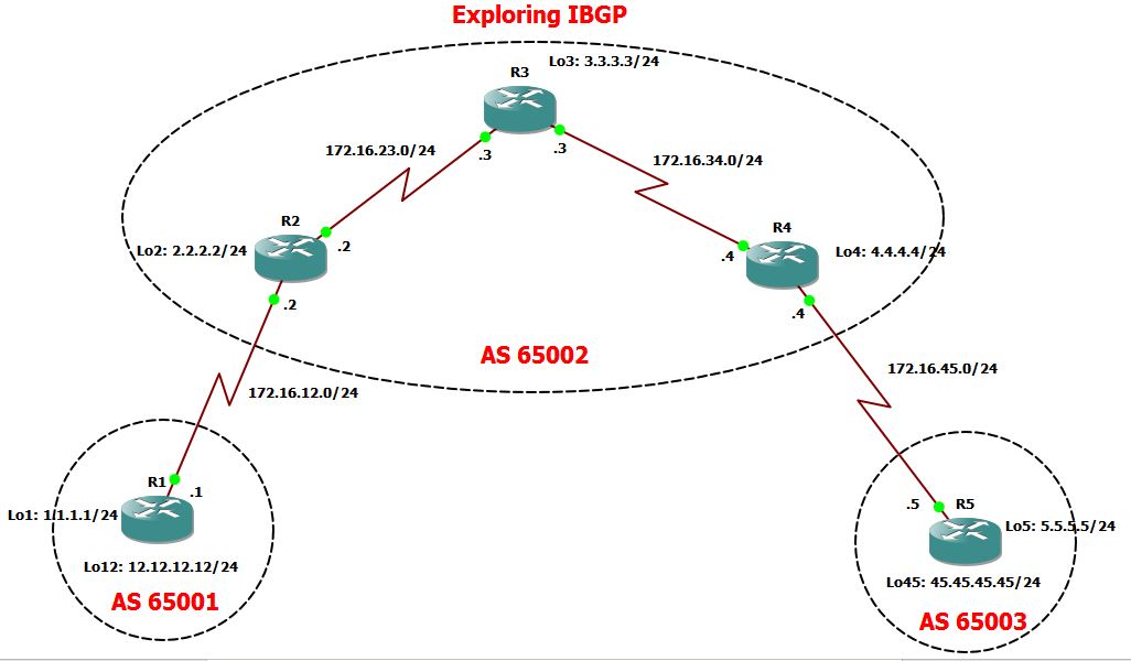
Laboratory Objective:
1. Setup EBGP between R1 and R2.
2. Configured IBGP on all routers within AS 65002. Used OSPF as the IGP..
3. Configure EBGP between R4 and R5
4. Test the connectivity between R1 Loopback 12 towards R5 Loopback 45.
Configuring the static routes on R1 & R2. This will ensure connections of the Loopback interfaces of both routers.
|
R1#sh run | sec ip route
ip route 2.2.2.2 255.255.255.255 172.16.12.2
R2#sh run | sec ip route
ip route 1.1.1.1 255.255.255.255 172.16.12.1
|
Let’s check if I can ping the Loopback interface:
|
R1#ping 2.2.2.2 source 1.1.1.1
Type escape sequence to abort.
Sending 5, 100-byte ICMP Echos to 2.2.2.2, timeout is 2 seconds:
Packet sent with a source address of 1.1.1.1
!!!!!
Success rate is 100 percent (5/5), round-trip min/avg/max = 52/60/76 ms
|
Let me established the EBGP between R1 and R2.
|
R1#sh run | sec bgp
ipv6 multicast rpf use-bgp
router bgp 65001
bgp log-neighbor-changes
network 12.12.12.0 mask 255.255.255.0
neighbor 2.2.2.2 remote-as 65002
neighbor 2.2.2.2 ebgp-multihop 2
neighbor 2.2.2.2 update-source Loopback1
R2#sh run | sec bgp
ipv6 multicast rpf use-bgp
router bgp 65002
bgp log-neighbor-changes
neighbor 1.1.1.1 remote-as 65001
neighbor 1.1.1.1 ebgp-multihop 2
neighbor 1.1.1.1 update-source Loopback2
|
So the EBGP neighbors between R1 and R2 were formed…
|
R1(config)#
*Oct 7 16:43:38.723: %BGP-5-ADJCHANGE: neighbor 2.2.2.2 Up
R2#
*Oct 7 16:43:35.823: %BGP-5-ADJCHANGE: neighbor 1.1.1.1 Up
|
As I advertise 12.12.12.0/24, it should be seen on R2 routing table.
|
R2#sh ip bgp
BGP table version is 3, local router ID is 2.2.2.2
Status codes: s suppressed, d damped, h history, * valid, > best, i – internal,
r RIB-failure, S Stale, m multipath, b backup-path, f RT-Filter,
x best-external, a additional-path, c RIB-compressed,
Origin codes: i – IGP, e – EGP, ? – incomplete
RPKI validation codes: V valid, I invalid, N Not found
Network Next Hop Metric LocPrf Weight Path
*> 12.12.12.0/24 1.1.1.1 0 0 65001 i
*> 172.16.12.0/24 0.0.0.0 0 32768 i
R2#show ip route bgp
!
Gateway of last resort is not set
12.0.0.0/24 is subnetted, 1 subnets
B 12.12.12.0 [20/0] via 1.1.1.1, 00:29:03
|
Let me set up the EBGP between R4 and R5.
|
R4#sh run | sec bgp
ipv6 multicast rpf use-bgp
router bgp 65002
bgp log-neighbor-changes
network 172.16.45.0 mask 255.255.255.0
neighbor 5.5.5.5 remote-as 65003
neighbor 5.5.5.5 ebgp-multihop 2
neighbor 5.5.5.5 update-source Loopback4
R5#sh run | sec bgp
ipv6 multicast rpf use-bgp
router bgp 65003
bgp log-neighbor-changes
network 45.45.45.0 mask 255.255.255.0
neighbor 4.4.4.4 remote-as 65002
neighbor 4.4.4.4 ebgp-multihop 2
neighbor 4.4.4.4 update-source Loopback5
|
EBGP neighbors were formed as shown below,
|
R4#
*Oct 7 16:58:42.039: %BGP-5-ADJCHANGE: neighbor 5.5.5.5 Up
R5#sh ip route 172.
*Oct 7 16:58:20.511: %BGP-5-ADJCHANGE: neighbor 4.4.4.4 Up
|
As I have advertised 45.45.45.0/24 on R5, it should be installed on R4 routing table. The BGP database also shows, it came from AS 65003.
|
R4#show ip bgp
BGP table version is 3, local router ID is 4.4.4.4
Status codes: s suppressed, d damped, h history, * valid, > best, i – internal,
r RIB-failure, S Stale, m multipath, b backup-path, f RT-Filter,
x best-external, a additional-path, c RIB-compressed,
Origin codes: i – IGP, e – EGP, ? – incomplete
RPKI validation codes: V valid, I invalid, N Not found
Network Next Hop Metric LocPrf Weight Path
*> 45.45.45.0/24 5.5.5.5 0 0 65003 i
*> 172.16.45.0/24 0.0.0.0 0 32768 i
R4#show ip route bgp
!
Gateway of last resort is not set
45.0.0.0/24 is subnetted, 1 subnets
B 45.45.45.0 [20/0] via 5.5.5.5, 00:02:16
|
Now, let me set up OSPF on Area 0 for R2, R3 and R4. Again, since I’m running IBGP, I need to have a full connectivity between IBGP routers which can only be done via IGP such as OSPF. I have advertise into OSPF the loopback interface of R2, R3 and R4 as this will be used as the source address for IBGP sessions.
|
R2#sh run | sec ospf
router ospf 1
network 2.2.2.2 0.0.0.0 area 0
network 172.16.23.0 0.0.0.255 area 0
R3#sh run | sec ospf
router ospf 1
network 172.16.23.0 0.0.0.255 area 0
network 172.16.34.0 0.0.0.255 area 0
R4#sh run | sec ospf
router ospf 1
network 4.4.4.4 0.0.0.0 area 0
network 172.16.34.0 0.0.0.255 area 0
|
Now, Let me check the OSPF neighbors.
|
R2#sho ip ospf neighbor
Neighbor ID Pri State Dead Time Address Interface
3.3.3.3 0 FULL/ – 00:00:32 172.16.23.3 Serial2/1
R3#show ip ospf neighbor
Neighbor ID Pri State Dead Time Address Interface
4.4.4.4 0 FULL/ – 00:00:29 172.16.34.4 Serial2/2
2.2.2.2 0 FULL/ – 00:00:29 172.16.23.2 Serial2/1
R4#show ip ospf neighbor
Neighbor ID Pri State Dead Time Address Interface
3.3.3.3 0 FULL/ – 00:00:39 172.16.34.3 Serial2/2
|
Alright, seems everything on the IGP network is working fine. let me test the connectivity to
ensure I have no issue later on…
|
So I can ping R4 loopback from R2..
R2#ping 4.4.4.4 source 2.2.2.2
Type escape sequence to abort.
Sending 5, 100-byte ICMP Echos to 4.4.4.4, timeout is 2 seconds:
Packet sent with a source address of 2.2.2.2
!!!!!
Success rate is 100 percent (5/5), round-trip min/avg/max = 76/80/84 ms
But I cannot ping R3 loopback from R2…
R2#ping 3.3.3.3 source 2.2.2.2
Type escape sequence to abort.
Sending 5, 100-byte ICMP Echos to 3.3.3.3, timeout is 2 seconds:
Packet sent with a source address of 2.2.2.2
…..
Success rate is 0 percent (0
But look at the comparison here. I don’t have the routes for 3.3.3.3/24 on R2.
R2#sh ip route 3.3.3.3
% Network not in table
R2#sh ip route 4.4.4.4
Routing entry for 4.4.4.4/32
Known via “ospf 1”, distance 110, metric 129, type intra area
Last update from 172.16.23.3 on Serial2/1, 00:04:05 ago
Routing Descriptor Blocks:
* 172.16.23.3, from 4.4.4.4, 00:04:05 ago, via Serial2/1
Route metric is 129, traffic share count is 1
Did some troubleshooting and it’s just a configs mistake, I forgot to advertise 3.3.3.3 into OSPF in R3.
R3#sh run | sec ospf
router ospf 1
network 172.16.23.0 0.0.0.255 area 0
network 172.16.34.0 0.0.0.255 area 0
R3#config t
Enter configuration commands, one per line. End with CNTL/Z.
R3(config)#router ospf 1
R3(config-router)#network 3.3.3.3 0.0.0.0 area 0
R3(config-router)#
By this time, I should be able to see the routes from both R2 and R4…
R2#sh ip route 3.3.3.3
Routing entry for 3.3.3.3/32
Known via “ospf 1”, distance 110, metric 65, type intra area
Last update from 172.16.23.3 on Serial2/1, 00:00:58 ago
Routing Descriptor Blocks:
* 172.16.23.3, from 3.3.3.3, 00:00:58 ago, via Serial2/1
Route metric is 65, traffic share count is 1
Let me try to ping now R3 from R2…
R2#ping 3.3.3.3 source 2.2.2.2
Type escape sequence to abort.
Sending 5, 100-byte ICMP Echos to 3.3.3.3, timeout is 2 seconds:
Packet sent with a source address of 2.2.2.2
!!!!!
Success rate is 100 percent (5/5), round-trip min/avg/max = 52/69/132 ms
|
Alright, it’s time for the IBGP Configurations
|
R2:
R2#sh run | sec bgp
ipv6 multicast rpf use-bgp
router bgp 65002
bgp log-neighbor-changes
network 172.16.12.0 mask 255.255.255.0
neighbor 1.1.1.1 remote-as 65001
neighbor 1.1.1.1 ebgp-multihop 2
neighbor 1.1.1.1 update-source Loopback2
neighbor 3.3.3.3 remote-as 65002
neighbor 3.3.3.3 update-source Loopback2
neighbor 4.4.4.4 remote-as 65002
neighbor 4.4.4.4 update-source Loopback2 neighbor 4.4.4.4 next-hop-self
R3:
R3#sh run | sec bgp
ipv6 multicast rpf use-bgp
router bgp 65002
bgp log-neighbor-changes
neighbor 2.2.2.2 remote-as 65002
neighbor 2.2.2.2 update-source Loopback3
neighbor 4.4.4.4 remote-as 65002
neighbor 4.4.4.4 update-source Loopback3
R4:
R4#sh run | sec bgp
ipv6 multicast rpf use-bgp
router bgp 65002
bgp log-neighbor-changes
network 172.16.45.0 mask 255.255.255.0
neighbor 2.2.2.2 remote-as 65002
neighbor 2.2.2.2 update-source Loopback4
neighbor 2.2.2.2 next-hop-self
neighbor 3.3.3.3 remote-as 65002
neighbor 3.3.3.3 update-source Loopback4
neighbor 5.5.5.5 remote-as 65003
neighbor 5.5.5.5 ebgp-multihop 2
neighbor 5.5.5.5 update-source Loopback4
|
|
* The UPDATE SOURCE command is used to tell the neighbor of the source of the BGP TCP Packet..
* The EBGP-Multihop is to increased the TTL value as we have used the loopback as the source of the
BGP packets.(Updates)…This will only used in External BGP.
* The new command NEXT-HOP -SELF which is set up in R2 and R4 is required to tell the neighbor that in order to reach a prefix outside of the AS, you have to used that router as the next hop..
|
Alright, lets check the IBGP neighbors…So it tells me below that the IBGP neighbors were
formed…
|
R2#sh ip bgp summary
BGP router identifier 2.2.2.2, local AS number 65002
BGP table version is 5, main routing table version 5
4 network entries using 576 bytes of memory
4 path entries using 320 bytes of memory
4/4 BGP path/bestpath attribute entries using 544 bytes of memory
2 BGP AS-PATH entries using 48 bytes of memory
0 BGP route-map cache entries using 0 bytes of memory
0 BGP filter-list cache entries using 0 bytes of memory
BGP using 1488 total bytes of memory
BGP activity 4/0 prefixes, 4/0 paths, scan interval 60 secs
Neighbor V AS MsgRcvd MsgSent TblVer InQ OutQ Up/Down State/PfxRcd
1.1.1.1 4 65001 62 65 5 0 0 00:53:16 1
3.3.3.3 4 65002 15 15 5 0 0 00:08:43 0
4.4.4.4 4 65002 22 22 5 0 0 00:14:52 2
R3#sh ip bgp summary
BGP router identifier 3.3.3.3, local AS number 65002
BGP table version is 3, main routing table version 3
4 network entries using 576 bytes of memory
4 path entries using 320 bytes of memory
3/1 BGP path/bestpath attribute entries using 408 bytes of memory
2 BGP AS-PATH entries using 48 bytes of memory
0 BGP route-map cache entries using 0 bytes of memory
0 BGP filter-list cache entries using 0 bytes of memory
BGP using 1352 total bytes of memory
BGP activity 4/0 prefixes, 4/0 paths, scan interval 60 secs
Neighbor V AS MsgRcvd MsgSent TblVer InQ OutQ Up/Down State/PfxRcd
2.2.2.2 4 65002 15 15 3 0 0 00:08:52 2
4.4.4.4 4 65002 15 14 3 0 0 00:08:54 2
R3#
R4#sh ip bgp summary
BGP router identifier 4.4.4.4, local AS number 65002
BGP table version is 5, main routing table version 5
4 network entries using 576 bytes of memory
4 path entries using 320 bytes of memory
4/4 BGP path/bestpath attribute entries using 544 bytes of memory
2 BGP AS-PATH entries using 48 bytes of memory
0 BGP route-map cache entries using 0 bytes of memory
0 BGP filter-list cache entries using 0 bytes of memory
BGP using 1488 total bytes of memory
BGP activity 4/0 prefixes, 4/0 paths, scan interval 60 secs
Neighbor V AS MsgRcvd MsgSent TblVer InQ OutQ Up/Down State/PfxRcd
2.2.2.2 4 65002 23 22 5 0 0 00:15:13 2
3.3.3.3 4 65002 14 15 5 0 0 00:09:04 0
5.5.5.5 4 65003 45 49 5 0 0 00:38:28 1
R4#
|
Now, let me go straight and check the connectivity between R1 and R5 loopback…Looking at the
BGP database and Routing Table in R1, I have the following entries…But let me try to ping from
R1…
|
R1#sh ip bgp
BGP table version is 5, local router ID is 12.12.12.12
Status codes: s suppressed, d damped, h history, * valid, > best, i – internal,
r RIB-failure, S Stale, m multipath, b backup-path, f RT-Filter,
x best-external, a additional-path, c RIB-compressed,
Origin codes: i – IGP, e – EGP, ? – incomplete
RPKI validation codes: V valid, I invalid, N Not found
Network Next Hop Metric LocPrf Weight Path
*> 12.12.12.0/24 0.0.0.0 0 32768 i
*> 45.45.45.0/24 2.2.2.2 0 65002 65003 i
r> 172.16.12.0/24 2.2.2.2 0 0 65002 i
*> 172.16.45.0/24 2.2.2.2 0 65002 i
R1#show ip route bgp
!
Gateway of last resort is not set
45.0.0.0/24 is subnetted, 1 subnets
B 45.45.45.0 [20/0] via 2.2.2.2, 00:16:54
172.16.0.0/16 is variably subnetted, 3 subnets, 2 masks
B 172.16.45.0/24 [20/0] via 2.2.2.2, 00:16:54
R1#ping 45.45.45.45
Type escape sequence to abort.
Sending 5, 100-byte ICMP Echos to 45.45.45.45, timeout is 2 seconds:
UUUUU
Success rate is 0 percent (0/5
|
So let’s check each hop… Looking at R2..It learned about 45.45.45.45 via IGP…meaning this
was advertise as a network under BGP and is from AS 65003..
|
R2#show ip bgp
BGP table version is 5, local router ID is 2.2.2.2
Status codes: s suppressed, d damped, h history, * valid, > best, i – internal,
r RIB-failure, S Stale, m multipath, b backup-path, f RT-Filter,
x best-external, a additional-path, c RIB-compressed,
Origin codes: i – IGP, e – EGP, ? – incomplete
RPKI validation codes: V valid, I invalid, N Not found
Network Next Hop Metric LocPrf Weight Path
*> 12.12.12.0/24 1.1.1.1 0 0 65001 i
*>i 45.45.45.0/24 4.4.4.4 0 100 0 65003 i
*> 172.16.12.0/24 0.0.0.0 0 32768 i
*>i 172.16.45.0/24 4.4.4.4 0 100 0 i
So it means R2 is picking up the routes..but when I do my traceroutes, it drops at R3…
R2#traceroute 45.45.45.45
Type escape sequence to abort.
Tracing the route to 45.45.45.45
VRF info: (vrf in name/id, vrf out name/id)
1 172.16.23.3 60 msec 52 msec 56 msec
2 172.16.23.3 !H !H !H
So let’s check R3….So with the BGP database for R3, it just tells me that 45.45.45.45 is an IGP routes
which is advertise as a network into BGP..seems okay but R3 does not have it it’s BGP routing table…
R3#sh ip bgp
BGP table version is 3, local router ID is 3.3.3.3
Status codes: s suppressed, d damped, h history, * valid, > best, i – internal,
r RIB-failure, S Stale, m multipath, b backup-path, f RT-Filter,
x best-external, a additional-path, c RIB-compressed,
Origin codes: i – IGP, e – EGP, ? – incomplete
RPKI validation codes: V valid, I invalid, N Not found
Network Next Hop Metric LocPrf Weight Path
* i 12.12.12.0/24 1.1.1.1 0 100 0 65001 i
* i 45.45.45.0/24 5.5.5.5 0 100 0 65003 i
*>i 172.16.12.0/24 2.2.2.2 0 100 0 i
*>i 172.16.45.0/24 4.4.4.4 0 100 0 i
R3#
R3#show ip route bgp
!
Gateway of last resort is not set
172.16.0.0/16 is variably subnetted, 6 subnets, 2 masks
B 172.16.12.0/24 [200/0] via 2.2.2.2, 00:17:15
B 172.16.45.0/24 [200/0] via 4.4.4.4, 00:17:17
R3#
There’e actually two issues here…
1. The Next hop address is via 5.5.5.5 which is R5 loopback address…But does R3 knows how to reach
5.5.5.5? I guess NO… Let see…
R3#show ip route 5.5.5.5
% Network not in table <<<<<< So it’s not in its routing table…
R3#
How can we fixed this????? let me answer this later on…What i wanted to do is to look at R4…So here is R4 BGP database….
R4#sho ip bgp
BGP table version is 5, local router ID is 4.4.4.4
Status codes: s suppressed, d damped, h history, * valid, > best, i – internal,
r RIB-failure, S Stale, m multipath, b backup-path, f RT-Filter,
x best-external, a additional-path, c RIB-compressed,
Origin codes: i – IGP, e – EGP, ? – incomplete
RPKI validation codes: V valid, I invalid, N Not found
Network Next Hop Metric LocPrf Weight Path
*>i 12.12.12.0/24 2.2.2.2 0 100 0 65001 i
*> 45.45.45.0/24 5.5.5.5 0 0 65003 i
*>i 172.16.12.0/24 2.2.2.2 0 100 0 i
*> 172.16.45.0/24 0.0.0.0 0 32768 i
So R4 can install this on its routing table as it’s a valid best route…( with the symbol *>)…
R4#show ip route bgp
!
Gateway of last resort is not set
12.0.0.0/24 is subnetted, 1 subnets
B 12.12.12.0 [200/0] via 2.2.2.2, 00:27:42
45.0.0.0/24 is subnetted, 1 subnets
B 45.45.45.0 [20/0] via 5.5.5.5, 00:35:22
172.16.0.0/16 is variably subnetted, 6 subnets, 2 masks
B 172.16.12.0/24 [200/0] via 2.2.2.2, 00:27:42
But why R3 is not installing the same routes …I think the answer is because, R3 doesn’t know about 5.5.5.5…Right?????
So the only options is to let R3 knows the next hop address of all routes that he learned from R4 should be R4 and not R5….So NEXT-HOP-SELF will be used to solved this issue…
R4#sh run | sec bgp
ipv6 multicast rpf use-bgp
router bgp 65002
bgp log-neighbor-changes
network 172.16.45.0 mask 255.255.255.0
neighbor 2.2.2.2 remote-as 65002
neighbor 2.2.2.2 update-source Loopback4
neighbor 2.2.2.2 next-hop-self
neighbor 3.3.3.3 remote-as 65002
neighbor 3.3.3.3 update-source Loopback4
neighbor 5.5.5.5 remote-as 65003
neighbor 5.5.5.5 ebgp-multihop 2
neighbor 5.5.5.5 update-source Loopback4
R4#
R4#
R4#config t
Enter configuration commands, one per line. End with CNTL/Z.
R4(config)#router bgp 65002
R4(config-router)#neighbor 3.3.3.3 next-hop-self
I need to clear BGP so it will have a new routes….I will do this in R3…
R3#clear ip bgp *
R3#
*Oct 7 17:53:05.983: %BGP-5-ADJCHANGE: neighbor 2.2.2.2 Down User reset
*Oct 7 17:53:05.983: %BGP_SESSION-5-ADJCHANGE: neighbor 2.2.2.2 IPv4 Unicast topology base removed from session User reset
*Oct 7 17:53:05.991: %BGP-5-ADJCHANGE: neighbor 4.4.4.4 Down User reset
*Oct 7 17:53:05.991: %BGP_SESSION-5-ADJCHANGE: neighbor 4.4.4.4 IPv4 Unicast topology base removed from session User reset
*Oct 7 17:53:06.531: %BGP-5-ADJCHANGE: neighbor 4.4.4.4 Up
*Oct 7 17:53:06.799: %BGP-5-ADJCHANGE: neighbor 2.2.2.2 Up
And now here’s comes the new NEXT HOP address which is 4.4.4.4 (R3) for the network 45.45.45.45/24.
R3#sh ip bgp
BGP table version is 1, local router ID is 3.3.3.3
Status codes: s suppressed, d damped, h history, * valid, > best, i – internal,
r RIB-failure, S Stale, m multipath, b backup-path, f RT-Filter,
x best-external, a additional-path, c RIB-compressed,
Origin codes: i – IGP, e – EGP, ? – incomplete
RPKI validation codes: V valid, I invalid, N Not found
Network Next Hop Metric LocPrf Weight Path
* i 12.12.12.0/24 1.1.1.1 0 100 0 65001 i
* i 45.45.45.0/24 4.4.4.4 0 100 0 65003 i
* i 172.16.12.0/24 2.2.2.2 0 100 0 i
* i 172.16.45.0/24 4.4.4.4 0 100 0 i
Traceroutes is still dropping at R4…
R3#traceroute 45.45.45.45
Type escape sequence to abort.
Tracing the route to 45.45.45.45
VRF info: (vrf in name/id, vrf out name/id)
1 172.16.34.4 56 msec 56 msec 52 msec
2 * * *
The reverse traceroutes towards R1 from R5 also drops at R3..
R5#traceroute 12.12.12.12
Type escape sequence to abort.
Tracing the route to 12.12.12.12
VRF info: (vrf in name/id, vrf out name/id)
1 172.16.45.4 [AS 65002] 56 msec 56 msec 52 msec
2 172.16.34.3 56 msec 52 msec 84 msec
3 172.16.34.3 !H !H !H
I think, I have missed one configs on R2 which is the NEXT-HOP-SELF to R3… R2 must tell his neighbor R3 that in order to reach 12.12.12.12.0/24 network, it has to go through him (R2)…
R2(config-router)#neighbor 3.3.3.3 next-hop-se
R2(config-router)#neighbor 3.3.3.3 next-hop-self
R2(config-router)#
Now, after few seconds, I was able to have full connectivity between R1 and R5…
R5#ping 12.12.12.12 source 45.45.45.45
Type escape sequence to abort.
Sending 5, 100-byte ICMP Echos to 12.12.12.12, timeout is 2 seconds:
Packet sent with a source address of 45.45.45.45
!!!!!
Success rate is 100 percent (5/5), round-trip min/avg/max = 104/108/116 ms
R5#
So here’s R5 BGP database…
R5#show ip bgp
BGP table version is 5, local router ID is 45.45.45.45
Status codes: s suppressed, d damped, h history, * valid, > best, i – internal,
r RIB-failure, S Stale, m multipath, b backup-path, f RT-Filter,
x best-external, a additional-path, c RIB-compressed,
Origin codes: i – IGP, e – EGP, ? – incomplete
RPKI validation codes: V valid, I invalid, N Not found
Network Next Hop Metric LocPrf Weight Path
*> 12.12.12.0/24 4.4.4.4 0 65002 65001 i
*> 45.45.45.0/24 0.0.0.0 0 32768 i
*> 172.16.12.0/24 4.4.4.4 0 65002 i
r> 172.16.45.0/24 4.4.4.4 0 0 65002 i
Here’s R1 BGP database…
R1#sho ip bgp
BGP table version is 5, local router ID is 12.12.12.12
Status codes: s suppressed, d damped, h history, * valid, > best, i – internal,
r RIB-failure, S Stale, m multipath, b backup-path, f RT-Filter,
x best-external, a additional-path, c RIB-compressed,
Origin codes: i – IGP, e – EGP, ? – incomplete
RPKI validation codes: V valid, I invalid, N Not found
Network Next Hop Metric LocPrf Weight Path
*> 12.12.12.0/24 0.0.0.0 0 32768 i
*> 45.45.45.0/24 2.2.2.2 0 65002 65003 i
r> 172.16.12.0/24 2.2.2.2 0 0 65002 i
*> 172.16.45.0/24 2.2.2.2 0 65002 i
Here’s R2 BGP database,
R2#show ip bgp
BGP table version is 5, local router ID is 2.2.2.2
Status codes: s suppressed, d damped, h history, * valid, > best, i – internal,
r RIB-failure, S Stale, m multipath, b backup-path, f RT-Filter,
x best-external, a additional-path, c RIB-compressed,
Origin codes: i – IGP, e – EGP, ? – incomplete
RPKI validation codes: V valid, I invalid, N Not found
Network Next Hop Metric LocPrf Weight Path
*> 12.12.12.0/24 1.1.1.1 0 0 65001 i
*>i 45.45.45.0/24 4.4.4.4 0 100 0 65003 i
*> 172.16.12.0/24 0.0.0.0 0 32768 i
*>i 172.16.45.0/24 4.4.4.4 0 100 0 i
R2#
Here’s R3 BGP database..
R3#show ip bgp
BGP table version is 5, local router ID is 3.3.3.3
Status codes: s suppressed, d damped, h history, * valid, > best, i – internal,
r RIB-failure, S Stale, m multipath, b backup-path, f RT-Filter,
x best-external, a additional-path, c RIB-compressed,
Origin codes: i – IGP, e – EGP, ? – incomplete
RPKI validation codes: V valid, I invalid, N Not found
Network Next Hop Metric LocPrf Weight Path
*>i 12.12.12.0/24 2.2.2.2 0 100 0 65001 i
*>i 45.45.45.0/24 4.4.4.4 0 100 0 65003 i
*>i 172.16.12.0/24 2.2.2.2 0 100 0 i
*>i 172.16.45.0/24 4.4.4.4 0 100 0 i
R3#
Here’s R4 BGP Database.
R4#show ip bgp
BGP table version is 5, local router ID is 4.4.4.4
Status codes: s suppressed, d damped, h history, * valid, > best, i – internal,
r RIB-failure, S Stale, m multipath, b backup-path, f RT-Filter,
x best-external, a additional-path, c RIB-compressed,
Origin codes: i – IGP, e – EGP, ? – incomplete
RPKI validation codes: V valid, I invalid, N Not found
Network Next Hop Metric LocPrf Weight Path
*>i 12.12.12.0/24 2.2.2.2 0 100 0 65001 i
*> 45.45.45.0/24 5.5.5.5 0 0 65003 i
*>i 172.16.12.0/24 2.2.2.2 0 100 0 i
*> 172.16.45.0/24 0.0.0.0 0 32768 i
R4#
|
Here are my final working BGP configs:
|
R1#sh run | sec bgp
ipv6 multicast rpf use-bgp
router bgp 65001
bgp log-neighbor-changes
network 12.12.12.0 mask 255.255.255.0
neighbor 2.2.2.2 remote-as 65002
neighbor 2.2.2.2 ebgp-multihop 2
neighbor 2.2.2.2 update-source Loopback1
R2#sh run | sec bgp
ipv6 multicast rpf use-bgp
router bgp 65002
bgp log-neighbor-changes
network 172.16.12.0 mask 255.255.255.0
neighbor 1.1.1.1 remote-as 65001
neighbor 1.1.1.1 ebgp-multihop 2
neighbor 1.1.1.1 update-source Loopback2
neighbor 3.3.3.3 remote-as 65002
neighbor 3.3.3.3 update-source Loopback2
neighbor 3.3.3.3 next-hop-self
neighbor 4.4.4.4 remote-as 65002
neighbor 4.4.4.4 next-hop-self
neighbor 4.4.4.4 update-source Loopback 2 R3#sh run | sec bgp
ipv6 multicast rpf use-bgp
router bgp 65002
bgp log-neighbor-changes
neighbor 2.2.2.2 remote-as 65002
neighbor 2.2.2.2 update-source Loopback3
neighbor 4.4.4.4 remote-as 65002
neighbor 4.4.4.4 update-source Loopback3
R3#
R4#sh run | sec bgp
ipv6 multicast rpf use-bgp
router bgp 65002
bgp log-neighbor-changes
network 172.16.45.0 mask 255.255.255.0
neighbor 2.2.2.2 remote-as 65002
neighbor 2.2.2.2 update-source Loopback4
neighbor 2.2.2.2 next-hop-self
neighbor 3.3.3.3 remote-as 65002
neighbor 3.3.3.3 update-source Loopback4
neighbor 3.3.3.3 next-hop-self
neighbor 5.5.5.5 remote-as 65003
neighbor 5.5.5.5 ebgp-multihop 2
neighbor 5.5.5.5 update-source Loopback4
R4#
R5#sh run | sec bgp
ipv6 multicast rpf use-bgp
router bgp 65003
bgp log-neighbor-changes
network 45.45.45.0 mask 255.255.255.0
neighbor 4.4.4.4 remote-as 65002
neighbor 4.4.4.4 ebgp-multihop 2
neighbor 4.4.4.4 update-source Loopback5
R5#
|
Finally, this ends my laboratory…. BGP is quite interesting to learned…….
*********************************END OF LAB************************************
EBGP-Multihop Explored
On this study notes, I’m going through a scenario on EBGP-MULTIHOP. My topology consist of two Routers that are connected via two serial connections. I will be establishing EBGP peering between this two routers using the Loopback interface.
Here is my topology for this laboratory,

Goal for this lab:
1. Established BGP peering using loopback interface
2. Increased the TTL value of both R1 and R2 to ensure that BGP source for TCP connections are using the loopback interface.
3. Set up the serials links and ensure that both are utilized.
Here are my router configurations:
|
R1:
R1#sh run | sec bgp
ipv6 multicast rpf use-bgp
router bgp 65000
bgp log-neighbor-changes
neighbor 20.20.20.20 remote-as 65001
neighbor 20.20.20.20 ebgp-multihop 2
neighbor 20.20.20.20 update-source Loopback1
|
|
R2:
R2#sh run | sec bgp
ipv6 multicast rpf use-bgp
router bgp 65001
bgp log-neighbor-changes
neighbor 10.10.10.10 remote-as 65000
neighbor 10.10.10.10 ebgp-multihop 2
neighbor 10.10.10.10 update-source Loopback2
|
|
Okay, two of the most important command for this scenario is the EBGP-MULTIHOP command and the “UPDATE-SOURCE” command.
EBGP-MULTIHOP is only implemented to formed EBGP neighbors and it is used to increased the TTL value. As routers will decreased the TTL value by default to 1, increasing it to TTL of 2 will ensure that the loopback interface which is used as the source for the BGP updates is reachable.
UPDATE-SOURCE command is used to tell to the peer which is the source of the BGP Packets ( Open, Update, Keepalive, and Notification).
|
A static route is required to ensure that the loopback is reachable from both ends..In this scenario, I have two interface connecting both routers so I have to used two static routes. Note that it is not required to be a static routes since the main objective is to provide connectivity to the Loopback interface from both sides for the reason mentioned above.
|
R1#sh run | inc ip route
ip route 20.20.20.0 255.255.255.0 172.16.12.2
ip route 20.20.20.0 255.255.255.0 192.168.12.2
R2#sh run | inc ip route
ip route 10.10.10.0 255.255.255.0 172.16.12.1
ip route 10.10.10.0 255.255.255.0 192.168.12.1
Checking the routing table:
R1#sh ip route
!
Gateway of last resort is not set
10.0.0.0/8 is variably subnetted, 2 subnets, 2 masks
C 10.10.10.0/24 is directly connected, Loopback1
L 10.10.10.10/32 is directly connected, Loopback1
20.0.0.0/24 is subnetted, 1 subnets
S 20.20.20.0 [1/0] via 192.168.12.2
[1/0] via 172.16.12.2
R2#show ip route
!
Gateway of last resort is not set
10.0.0.0/24 is subnetted, 1 subnets
S 10.10.10.0 [1/0] via 192.168.12.1
[1/0] via 172.16.12.1
|
Checking the BGP neighbor using the “show ip bgp summary” command:
|
R1#sh ip bgp summary
BGP router identifier 10.10.10.10, local AS number 65000
BGP table version is 1, main routing table version 1
Neighbor V AS MsgRcvd MsgSent TblVer InQ OutQ Up/Down State/PfxRcd
20.20.20.20 4 65001 6 6 1 0 0 00:02:45 0
R2#show ip bgp summary
BGP router identifier 20.20.20.20, local AS number 65001
BGP table version is 1, main routing table version 1
Neighbor V AS MsgRcvd MsgSent TblVer InQ OutQ Up/Down State/PfxRcd
10.10.10.10 4 65000 7 7 1 0 0 00:02:55 0
|
Checking the BGP database and as expected, there’s no BGP database yet as I did not advertise
anything yet.
|
R1#show ip bgp
R1#
R2#sh ip bgp
R2#
Let me create a Loopback 10 on R1 with the network 100.100.100.100/24 network and advertise it to BGP.
R1(config)#int lo10
R1(config-if)#ip address 100.100.100.100 255.255.255.0
R1(config)#router bgp 65000
R1(config-router)#network 100.100.100.0 mask 255.255.255.0
R1(config-router)#^Z
Now, checking the BGP database on R1:
R1#show ip bgp
BGP table version is 2, local router ID is 10.10.10.10
Status codes: s suppressed, d damped, h history, * valid, > best, i – internal,
r RIB-failure, S Stale, m multipath, b backup-path, f RT-Filter,
x best-external, a additional-path, c RIB-compressed,
Origin codes: i – IGP, e – EGP, ? – incomplete
RPKI validation codes: V valid, I invalid, N Not found
Network Next Hop Metric LocPrf Weight Path
*> 100.100.100.0/24 0.0.0.0 0 32768 i
R1#
Let’s check whether this is propagated in R2.
R2#show ip bgp
BGP table version is 2, local router ID is 20.20.20.20
Status codes: s suppressed, d damped, h history, * valid, > best, i – internal,
r RIB-failure, S Stale, m multipath, b backup-path, f RT-Filter,
x best-external, a additional-path, c RIB-compressed,
Origin codes: i – IGP, e – EGP, ? – incomplete
RPKI validation codes: V valid, I invalid, N Not found
Network Next Hop Metric LocPrf Weight Path
*> 100.100.100.0/24 10.10.10.10 0 0 65000 i
R2#
So it shows that 100.100.100.100/24 is reachable via 10.10.10.10 with the AS of 65000. As this the best valid routes, it will be installed on R2 Routing table.
R2#show ip route bgp
Codes: L – local, C – connected, S – static, R – RIP, M – mobile, B – BGP
D – EIGRP, EX – EIGRP external, O – OSPF, IA – OSPF inter area
N1 – OSPF NSSA external type 1, N2 – OSPF NSSA external type 2
E1 – OSPF external type 1, E2 – OSPF external type 2
i – IS-IS, su – IS-IS summary, L1 – IS-IS level-1, L2 – IS-IS level-2
ia – IS-IS inter area, * – candidate default, U – per-user static route
o – ODR, P – periodic downloaded static route, H – NHRP, l – LISP
+ – replicated route, % – next hop override
Gateway of last resort is not set
100.0.0.0/24 is subnetted, 1 subnets
B 100.100.100.0 [20/0] via 10.10.10.10, 00:03:55
R2#
|
BGP States
On this study notes, I will be going through in details of the 6 States on how BGP adjacency were formed.
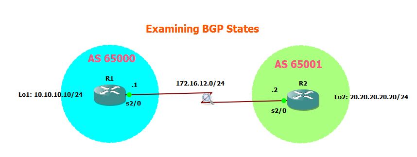
Objective: Understand the 6 BGP States.
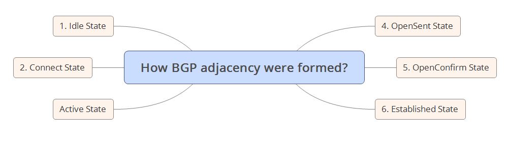
Above shows the 6 BGP States in Sequence. But before, going through it on details, I have configured the topology above and will just show how the adjacencies were formed after enabling the neighbor command under BGP process.
|
R2(config-router)#
*Oct 6 19:31:13.242: BGP: nbr global 172.16.12.1 Active open failed – can’t get active topologies *Oct 6 19:31:23.234: BGP: topo global:MVPNv4 Unicast:base Scanning routing tables |
| Analysis, 1. As we can see above, R1 is initiating the Passive Open connections to R2. 2. R2 switched from Idle to Connect. In the Idle state, no BGP resources are allocated to any of the peers. When the BGP state switched to Connect, peers are waiting to complete the TCP three way handshake. 3. Once the TCP 3 way handshake is completed, we can also see that the OPEN Packet parameters were exchange and has to be agreed on both R1 and R2. 3. We can also see that from Connect, it switch to OpenSent. On this state, the BGP waits for an OpenMessage from its peers. 4. The OpenConfirm State waits for the Keepalive or Notifications messages. 5. If the Keepalive is received , the state will be changed to Established. |
Below is the debug output on R1:
|
*Oct 6 20:43:03.362: BGP: ses global 172.16.12.2 (0x67C81B04:1) Removed topology IPv4 Unicast:base
*Oct 6 20:43:03.362: BGP: ses global 172.16.12.2 (0x67C81B04:1) Removed last topology
*Oct 6 20:43:03.366: BGP: nbr global 172.16.12.2 Open active delayed 11264ms (35000ms max, 60% jitter)
*Oct 6 20:43:03.366: BGP: nbr global 172.16.12.2 Active open failed – open timer running
R1#
*Oct 6 20:43:14.386: BGP: 172.16.12.2 active went from Idle to Active
*Oct 6 20:43:14.390: BGP: 172.16.12.2 open active, local address 172.16.12.1
*Oct 6 20:43:14.446: BGP: 172.16.12.2 open failed: Connection refused by remote host
*Oct 6 20:43:14.446: BGP: 172.16.12.2 Active open failed – tcb is not available, open active delayed 7168ms (35000ms max, 60% jitter )
*Oct 6 20:43:14.450: BGP: ses global 172.16.12.2 (0x67C81C5C:0) act Reset (Active open failed).
*Oct 6 20:43:14.458: BGP: 172.16.12.2 active went from Active to Idle
*Oct 6 20:43:14.458: BGP: nbr global 172.16.12.2 Active open failed – open timer running
R1#
*Oct 6 20:43:14.462: BGP: nbr global 172.16.12.2 Active open failed – open timer running
R1#
*Oct 6 20:43:21.586: BGP: 172.16.12.2 active went from Idle to Active
*Oct 6 20:43:21.590: BGP: 172.16.12.2 open active, local address 172.16.12.1
*Oct 6 20:43:21.670: BGP: ses global 172.16.12.2 (0x67C81C5C:0) act Adding topology IPv4 Unicast:base
*Oct 6 20:43:21.674: BGP: ses global 172.16.12.2 (0x67C81C5C:0) act Send OPEN
*Oct 6 20:43:21.674: BGP: ses global 172.16.12.2 (0x67C81C5C:0) act Building Enhanced Refresh capability
*Oct 6 20:43:21.678: BGP: 172.16.12.2 active went from Active to OpenSent
*Oct 6 20:43:21.678: BGP: 172.16.12.2 active sending OPEN, version 4, my as: 65000, holdtime 180 seconds, ID A0A0A0A
*Oct 6 20:43:21.814: BGP: 172.16.12.2 active rcv message type 1, length (excl. header) 38
*Oct 6 20:43:21.818: BGP: ses global 172.16.12.2 (0x67C81C5C:0) act Receive OPEN
*Oct 6 20:43:21.818: BGP: 172.16.12.2 active rcv OPEN, version 4, holdtime 180 seconds
*Oct 6 20:43:21.822: BGP: 172.16.12.2 active rcv OPEN w/ OPTION parameter len: 28
*Oct 6 20:4
R1#3:21.822: BGP: 172.16.12.2 active rcvd OPEN w/ optional parameter type 2 (Capability) len 6
*Oct 6 20:43:21.822: BGP: 172.16.12.2 active OPEN has CAPABILITY code: 1, length 4
*Oct 6 20:43:21.826: BGP: 172.16.12.2 active OPEN has MP_EXT CAP for afi/safi: 1/1
*Oct 6 20:43:21.826: BGP: 172.16.12.2 active rcvd OPEN w/ optional parameter type 2 (Capability) len 2
*Oct 6 20:43:21.830: BGP: 172.16.12.2 active OPEN has CAPABILITY code: 128, length 0
*Oct 6 20:43:21.830: BGP: 172.16.12.2 active OPEN has ROUTE-REFRESH capability(old) for all address-families
*Oct 6 20:43:21.830: BGP: 172.16.12.2 active rcvd OPEN w/ optional parameter type 2 (Capability) len 2
*Oct 6 20:43:21.834: BGP: 172.16.12.2 active OPEN has CAPABILITY code: 2, length 0
*Oct 6 20:43:21.834: BGP: 172.16.12.2 active OPEN has ROUTE-REFRESH capability(new) for all address-families
*Oct 6 20:43:21.834: BGP: 172.16.12.2 active rcvd OPEN w/ optional parameter type 2 (Capability) len 2
*Oct 6 20:43:21.838: BGP:
R1#172.16.12.2 active OPEN has CAPABILITY code: 70, length 0
*Oct 6 20:43:21.838: BGP: ses global 172.16.12.2 (0x67C81C5C:0) act Enhanced Refresh cap received in open message
*Oct 6 20:43:21.842: BGP: 172.16.12.2 active rcvd OPEN w/ optional parameter type 2 (Capability) len 6
*Oct 6 20:43:21.842: BGP: 172.16.12.2 active OPEN has CAPABILITY code: 65, length 4
*Oct 6 20:43:21.842: BGP: 172.16.12.2 active OPEN has 4-byte ASN CAP for: 65001
*Oct 6 20:43:21.846: BGP: nbr global 172.16.12.2 neighbor does not have IPv4 MDT topology activated
*Oct 6 20:43:21.846: BGP: 172.16.12.2 active rcvd OPEN w/ remote AS 65001, 4-byte remote AS 65001
*Oct 6 20:43:21.850: BGP: 172.16.12.2 active went from OpenSent to OpenConfirm
*Oct 6 20:43:21.850: BGP: 172.16.12.2 active went from OpenConfirm to Established
*Oct 6 20:43:21.854: BGP: ses global 172.16.12.2 (0x67C81C5C:1) act Assigned ID
*Oct 6 20:43:21.854: BGP: ses global 172.16.12.2 (0x67C81C5C:1) Up
*Oct 6 20:43:21.858: %BGP-5-ADJC
R1#HANGE: neighbor 172.16.12.2 Up
*Oct 6 20:43:21.866: BGP: ses global 172.16.12.2 (0x67C81C5C:1) read request no-op
R1#
*Oct 6 20:43:51.878: BGP: topo global:IPv4 Unicast:base Scanning routing tables
*Oct 6 20:43:51.882: BGP: topo global:IPv4 Multicast:base Scanning routing tables
*Oct 6 20:43:51.882: BGP: topo global:MVPNv4 Unicast:base Scanning routing tables
R1#
|
|
Let me go through on the debug output on R1 to look at another views on the BGP States:
1. R1 switch from Idle State to Active State.
2. From Active State, it switch to OpenSent.
3. OpenSent to OpenConfirm.
4. OpenConfirm to Established.
|
Let me go through the details of each of the 6 BGP States:

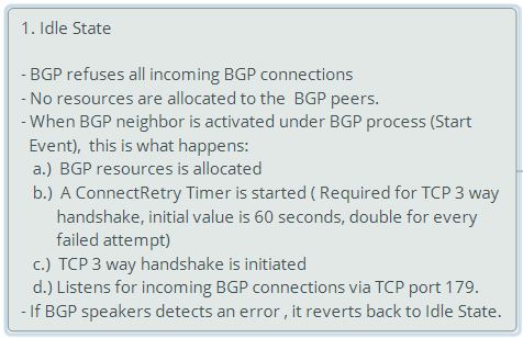
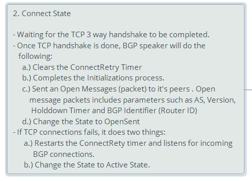
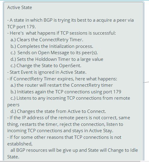


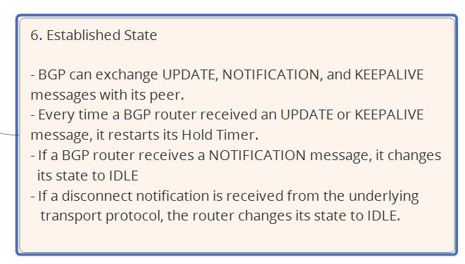
**************************END***************************************************
BGP Packets
This is another series of my BGP study notes. On this post, I will be going through the deep details of BGP Packets analysis using wireshark.
Here is my topology for this laboratory:
Objective: To understand the BGP Packet types.
Let me show the BGP configurations of both R1 and R2 first before going into the details of the BGP packet types.
R1 Configurations:
|
R1#sh run | sec bgp
ipv6 multicast rpf use-bgp
router bgp 65000
bgp log-neighbor-changes
network 10.10.10.0 mask 255.255.255.0
neighbor 172.16.12.2 remote-as 65001
|
R2 Configurations:
|
R2#sh run | sec bgp
ipv6 multicast rpf use-bgp
router bgp 65001
bgp log-neighbor-changes
network 20.20.20.0 mask 255.255.255.0
neighbor 172.16.12.1 remote-as 65000
|
The moment that I have enabled the network on R1 and R2, the BGP neighbors were formed.
|
R1#
*Oct 6 14:22:59.123: %BGP-5-ADJCHANGE: neighbor 172.16.12.2 Up
R2(config-router)#
*Oct 6 14:22:58.675: %BGP-5-ADJCHANGE: neighbor 172.16.12.1 Up
|
Checking the status of the BGP neighbor using the command ” show ip bgp summary“:
|
R1#sh ip bgp summary
BGP router identifier 10.10.10.10, local AS number 65000
BGP table version is 7, main routing table version 7
2 network entries using 288 bytes of memory
2 path entries using 160 bytes of memory
2/2 BGP path/bestpath attribute entries using 272 bytes of memory
1 BGP AS-PATH entries using 24 bytes of memory
0 BGP route-map cache entries using 0 bytes of memory
0 BGP filter-list cache entries using 0 bytes of memory
BGP using 744 total bytes of memory
BGP activity 4/2 prefixes, 4/2 paths, scan interval 60 secs
Neighbor V AS MsgRcvd MsgSent TblVer InQ OutQ Up/Down State/PfxRcd
172.16.12.2 4 65001 31 30 7 0 0 00:23:16 1
R1#
|
Let’s check the BGP database using the command “show ip bgp“.
|
R1#show ip bgp
BGP table version is 7, local router ID is 10.10.10.10
Status codes: s suppressed, d damped, h history, * valid, > best, i – internal,
r RIB-failure, S Stale, m multipath, b backup-path, f RT-Filter,
x best-external, a additional-path, c RIB-compressed,
Origin codes: i – IGP, e – EGP, ? – incomplete
RPKI validation codes: V valid, I invalid, N Not found
Network Next Hop Metric LocPrf Weight Path
*> 10.10.10.0/24 0.0.0.0 0 32768 i
*> 20.20.20.0/24 172.16.12.2 0 0 65001 i
|
|
Learning Points:
As seen from the results of “show ip bgp“, it does tells the following information:
1. That the network 10.10.10.0/24 is a valid route (*) and best routes (>) in which the next hop 0.0.0.0 is telling us that the network is originated from R1.
2. The default Weight is 32768 as it was advertise from the local router R1.
3. The network 20.20.20.0/24 is a valid route (*) and best route (>) which is reachable via 172.16.12.2
and it was advertised from AS 65001.
4. The > means that it’s the best path towards the destination network and it will be installed on the
routing table.
|
Let’s check the routing table:
|
R1#show ip route bgp
Codes: L – local, C – connected, S – static, R – RIP, M – mobile, B – BGP
D – EIGRP, EX – EIGRP external, O – OSPF, IA – OSPF inter area
N1 – OSPF NSSA external type 1, N2 – OSPF NSSA external type 2
E1 – OSPF external type 1, E2 – OSPF external type 2
i – IS-IS, su – IS-IS summary, L1 – IS-IS level-1, L2 – IS-IS level-2
ia – IS-IS inter area, * – candidate default, U – per-user static route
o – ODR, P – periodic downloaded static route, H – NHRP, l – LISP
+ – replicated route, % – next hop override
Gateway of last resort is not set
20.0.0.0/24 is subnetted, 1 subnets
B 20.20.20.0 [20/0] via 172.16.12.2, 00:31:33
|
That’s just an overview about how BGP peering is created, how to check whether the BGP neighbors were formed , checking the BGP database and how to check the valid routes and best routes and to understand that when a routes have *> it means that this will be installed on the routing table. Let me go through the deep packet level analysis of BGP.
So here’s the 4 BGP Packet Types…
Let me capture the BGP TCP sessions using a wireshark to get a detailed information on the BGP packet types.
First, let me shutdown BGP neighbors in R2, enabled it back and capture the traffic using wireshark.
First, let me shutdown BGP neighbors in R2, enabled it back and capture the traffic using wireshark.
|
R2(config-router)#neighbor 172.16.12.1 shutdown
*Oct 6 14:59:20.655: %BGP-5-NBR_RESET: Neighbor 172.16.12.1 reset (Admin. shutdown)
*Oct 6 14:59:20.671: %BGP-5-ADJCHANGE: neighbor 172.16.12.1 Down Admin. shutdown
*Oct 6 14:59:20.671: %BGP_SESSION-5-ADJCHANGE: neighbor 172.16.12.1 IPv4 Unicast topology base removed from session Admin. shutdown
Enabling back:
R2(config-router)#no neighbor 172.16.12.1 shutdown
*Oct 6 14:59:46.615: %BGP-5-ADJCHANGE: neighbor 172.16.12.1 Up
|
|
Below is the wireshark capture about BGP packet types. Let me to go through the results.
1. BGP using TCP 179 to established connections.
2. BGP uses the TCP three-way handshake to established the BGP sessions.
3. Once the Three-way handshake is completed, Open Message were exchange between R1 and R2. Open messages will contained parameters such as BGP Version, AS number, Hold Time, and BGP
Identifer and some other optional parameters.
4. Keepalive Messages were exchange between R1 and R2. The main purposed is to ensure that both routers are reachable. By default BGP keepalive is sent every 60 seconds and if the neighbor did not received a keepalive messaged within 180 seconds, it will flush the routes on its routing table.
5. The Update Message means that’s the BGP neighbors have started exchanging routing information. From the Wireshark results, we can see the information such as Widrawn routes, Total Path Attribute Length, Path Attributes, NLRI details…
|

Taking a closer look on the Open Message
|
Below is the information’s included in the Open Message:
1. Version ( in this case is BGP version 4)
2. AS Number ( AS number of R1 which is 65000)
3. Hold Time ( 180 seconds or 3 times the Keepalive message)
4. BGP Identifier ( As I’m looking at the open message on R1, this is the Loopback 1 address)
5. Optional Parameters ,e.g. Route refresh capability, Multiprotocol extensions,
|

Let’s take a closer look also on the Keepalive Message: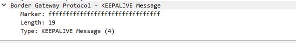
|
Learning Points:
1. So keepalive has a total length of 19 bytes 2. Keepalive is send every 60 seconds. |
So what about the Update Message
|
So what’s inside the capture message?
1. Marker, length, widrawn routes, total length attributes, path attributes. Network Layer Reachability
Informations (NRLI)..
2. NRLI is simply just the prefix that is advertise into BGP.
3. We can also notice that on the Path Attributes, we have seen the attribute flags..
4. Based on the attribute flag, Origin is a Transitive, AS Path is also Transitive, Next Hop Attribute is Transitive while MED or metrics attribute is Optional.
|


The last BGP packet which is Notification Message is sent out when the BGP neighbors were terminated.
Let me change the AS of R2 to generate a notification message.
|
R2(config-router)#router bgp 65002
R2(config-router)#neighbor 172.16.12.1 remote-as 65000
R2(config-router)#
|

|
Learning points:
1. As observed above, the Notification message Error Code shows as Bad Peer AS.
2. Other potential errors might include BGP identifier is incorrect, Hold Time is different from the BGP peers, or the BGP Version does not match. If we can notice this are the same parameters which were negotiated in the Open Message.
|
*********************************End of Lab****************************************
BGP Weight Attribute Explained (Part 2)
This is another post about BGP Weight Attributes.
|
Objective:
1. Established EBGP peering using two methods.
2. Implement a policy for so that all networks on R4 will take the path via R3.
|
Topology:
R1 BGP Configurations:
|
R1#sh run | sec bgp
router bgp 1 bgp log-neighbor-changes network 100.100.100.100 mask 255.255.255.255 neighbor 2.2.2.2 remote-as 2 <<<< Method # 1 to create BGP peering neighbor 2.2.2.2 ebgp-multihop 10 neighbor 2.2.2.2 update-source Loopback0 neighbor 192.168.13.3 remote-as 2 <<< Method # 2 to create BGP peering |
Static Route in R1 and R2:
|
R1#sh run | inc ip route
ip route 2.2.2.2 255.255.255.255 192.168.12.2 R2#sh run | inc ip route
ip route 1.1.1.1 255.255.255.255 192.168.12.1 |
IGP Configs on R2:
|
R2#sh run | sec ospf
router ospf 1 network 2.2.2.2 0.0.0.0 area 0 network 192.168.24.0 0.0.0.255 area 0 |
IBGP Configs on R2:
|
R2#sh run | sec bgp
router bgp 2 bgp log-neighbor-changes network 192.168.12.0 neighbor 1.1.1.1 remote-as 1 <<< Method # 1 to create BGP peering neighbor 1.1.1.1 ebgp-multihop 10 neighbor 1.1.1.1 update-source Loopback0 neighbor 3.3.3.3 remote-as 2 neighbor 3.3.3.3 update-source Loopback0 neighbor 4.4.4.4 remote-as 2 neighbor 4.4.4.4 update-source Loopback0 neighbor 4.4.4.4 next-hop-self |
IGP Configs on R3:
|
R3#sh run | sec ospf
router ospf 1 network 3.3.3.3 0.0.0.0 area 0 network 192.168.34.0 0.0.0.255 area 0 |
IBGP Configs on R3:
|
R3#sh run | sec bgp
router bgp 2 bgp log-neighbor-changes neighbor 2.2.2.2 remote-as 2 neighbor 2.2.2.2 update-source Loopback0 neighbor 4.4.4.4 remote-as 2 neighbor 4.4.4.4 update-source Loopback0 neighbor 4.4.4.4 next-hop-self neighbor 192.168.13.1 remote-as 1 |
IGP Configs on R4:
|
R4#sh run | sec ospf
router ospf 1 network 4.4.4.4 0.0.0.0 area 0 network 192.168.24.0 0.0.0.255 area 0 network 192.168.34.0 0.0.0.255 area 0 |
BGP Configs on R4:
|
R4#sh run | sec bgp
router bgp 2 bgp log-neighbor-changes network 11.11.11.11 mask 255.255.255.255 network 22.22.22.22 mask 255.255.255.255 network 33.33.33.33 mask 255.255.255.255 network 44.44.44.44 mask 255.255.255.255 neighbor 2.2.2.2 remote-as 2 neighbor 2.2.2.2 update-source Loopback0 neighbor 3.3.3.3 remote-as 2 neighbor 3.3.3.3 update-source Loopback0 |
Checking OSPF Neighbors:
|
R2#show ip ospf neighbor
Neighbor ID Pri State Dead Time Address Interface 44.44.44.44 0 FULL/ – 00:00:36 192.168.24.4 Serial3/2 R3# show ip ospf neighbor
Neighbor ID Pri State Dead Time Address Interface 44.44.44.44 0 FULL/ – 00:00:32 192.168.34.4 Serial3/3 R4#show ip ospf neighbor
Neighbor ID Pri State Dead Time Address Interface 3.3.3.3 0 FULL/ – 00:00:38 192.168.34.3 Serial3/3 2.2.2.2 0 FULL/ – 00:00:32 192.168.24.2 Serial3/2 |
Checking BGP Neighbors:
|
R1#sh ip bgp summary
BGP router identifier 100.100.100.100, local AS number 1 BGP table version is 6, main routing table version 6 5 network entries using 720 bytes of memory 5 path entries using 400 bytes of memory 2/2 BGP path/bestpath attribute entries using 272 bytes of memory 1 BGP AS-PATH entries using 24 bytes of memory 0 BGP route-map cache entries using 0 bytes of memory 0 BGP filter-list cache entries using 0 bytes of memory BGP using 1416 total bytes of memory BGP activity 5/0 prefixes, 5/0 paths, scan interval 60 secs Neighbor V AS MsgRcvd MsgSent TblVer InQ OutQ Up/Down State/PfxRcd R2#sh ip bgp summary
BGP router identifier 2.2.2.2, local AS number 2 BGP table version is 7, main routing table version 7 6 network entries using 864 bytes of memory 7 path entries using 560 bytes of memory 4/3 BGP path/bestpath attribute entries using 544 bytes of memory 1 BGP AS-PATH entries using 24 bytes of memory 0 BGP route-map cache entries using 0 bytes of memory 0 BGP filter-list cache entries using 0 bytes of memory BGP using 1992 total bytes of memory BGP activity 6/0 prefixes, 7/0 paths, scan interval 60 secs Neighbor V AS MsgRcvd MsgSent TblVer InQ OutQ Up/Down State/PfxRcd R3#show ip bgp summary
BGP router identifier 3.3.3.3, local AS number 2 BGP table version is 7, main routing table version 7 6 network entries using 864 bytes of memory 7 path entries using 560 bytes of memory 3/2 BGP path/bestpath attribute entries using 408 bytes of memory 1 BGP AS-PATH entries using 24 bytes of memory 0 BGP route-map cache entries using 0 bytes of memory 0 BGP filter-list cache entries using 0 bytes of memory BGP using 1856 total bytes of memory BGP activity 6/0 prefixes, 7/0 paths, scan interval 60 secs Neighbor V AS MsgRcvd MsgSent TblVer InQ OutQ Up/Down State/PfxRcd R4#show ip bgp summary
BGP router identifier 44.44.44.44, local AS number 2 BGP table version is 8, main routing table version 8 6 network entries using 864 bytes of memory 7 path entries using 560 bytes of memory 3/3 BGP path/bestpath attribute entries using 408 bytes of memory 1 BGP AS-PATH entries using 24 bytes of memory 0 BGP route-map cache entries using 0 bytes of memory 0 BGP filter-list cache entries using 0 bytes of memory BGP using 1856 total bytes of memory BGP activity 6/0 prefixes, 7/0 paths, scan interval 60 secs Neighbor V AS MsgRcvd MsgSent TblVer InQ OutQ Up/Down State/PfxRcd |
Checking the BGP Topology
|
R1#sh ip bgp
BGP table version is 6, local router ID is 100.100.100.100 Status codes: s suppressed, d damped, h history, * valid, > best, i – internal, r RIB-failure, S Stale, m multipath, b backup-path, f RT-Filter, x best-external, a additional-path, c RIB-compressed, Origin codes: i – IGP, e – EGP, ? – incomplete RPKI validation codes: V valid, I invalid, N Not found Network Next Hop Metric LocPrf Weight Path R2#sh ip bgp
BGP table version is 9, local router ID is 2.2.2.2 Status codes: s suppressed, d damped, h history, * valid, > best, i – internal, r RIB-failure, S Stale, m multipath, b backup-path, f RT-Filter, x best-external, a additional-path, c RIB-compressed, Origin codes: i – IGP, e – EGP, ? – incomplete RPKI validation codes: V valid, I invalid, N Not found Network Next Hop Metric LocPrf Weight Path R3#show ip bgp
BGP table version is 9, local router ID is 3.3.3.3 Status codes: s suppressed, d damped, h history, * valid, > best, i – internal, r RIB-failure, S Stale, m multipath, b backup-path, f RT-Filter, x best-external, a additional-path, c RIB-compressed, Origin codes: i – IGP, e – EGP, ? – incomplete RPKI validation codes: V valid, I invalid, N Not found Network Next Hop Metric LocPrf Weight Path R4#show ip bgp
BGP table version is 11, local router ID is 44.44.44.44 Status codes: s suppressed, d damped, h history, * valid, > best, i – internal, r RIB-failure, S Stale, m multipath, b backup-path, f RT-Filter, x best-external, a additional-path, c RIB-compressed, Origin codes: i – IGP, e – EGP, ? – incomplete RPKI validation codes: V valid, I invalid, N Not found Network Next Hop Metric LocPrf Weight Path |
Let’s check the routing table on R1:
|
R1#show ip route bgp
Codes: L – local, C – connected, S – static, R – RIP, M – mobile, B – BGP D – EIGRP, EX – EIGRP external, O – OSPF, IA – OSPF inter area N1 – OSPF NSSA external type 1, N2 – OSPF NSSA external type 2 E1 – OSPF external type 1, E2 – OSPF external type 2 i – IS-IS, su – IS-IS summary, L1 – IS-IS level-1, L2 – IS-IS level-2 ia – IS-IS inter area, * – candidate default, U – per-user static route o – ODR, P – periodic downloaded static route, H – NHRP, l – LISP + – replicated route, % – next hop override Gateway of last resort is not set 11.0.0.0/32 is subnetted, 1 subnets ** As observed, the paths towards R4 network is via R2.
|
To satisfy the second objective, I’m creating a route-map to influence the path towards R3:
|
R1(config)#route-map SET-WEIGHT-R3 permit 10
R1(config-route-map)#set weigh R1(config-route-map)#set weight 500 R1(config-route-map)#match ip address 1 ** I have increased the weight to 500 ..the default weight is 0. By setting the weight to higher value than 0, then it will prefer the path with higher weight attribute”
|
Here’s the access-list that will be used for the route-map SET-WEIGHT-R3
|
R1(config)#access-list 1 permit 11.11.11.11 0.0.0.0
R1(config)#access-list 1 permit 22.22.22.22 0.0.0.0 R1(config)#access-list 1 permit 33.33.33.33 0.0.0.0 R1(config)#access-list 1 permit 44.44.44.44 0.0.0.0 |
Apply the route-map on R1 to R3 BGP peering.
|
R1(config)#router bgp 1
R1(config-router)#neighbor 192.168.13.3 route-map SET-WEIGHT-R3 in |
Now, let’s check the new BGP topology after clearing BGP.
|
R1#clear ip bgp *
R1# *Sep 21 22:38:43.363: %BGP-5-ADJCHANGE: neighbor 2.2.2.2 Down User reset *Sep 21 22:38:43.363: %BGP_SESSION-5-ADJCHANGE: neighbor 2.2.2.2 IPv4 Unicast topology base removed from session User reset *Sep 21 22:38:43.371: %BGP-5-ADJCHANGE: neighbor 192.168.13.3 Down User reset *Sep 21 22:38:43.375: %BGP_SESSION-5-ADJCHANGE: neighbor 192.168.13.3 IPv4 Unicast topology base removed from session User reset *Sep 21 22:38:43.871: %BGP-5-ADJCHANGE: neighbor 192.168.13.3 Up *Sep 21 22:38:43.875: %BGP-5-ADJCHANGE: neighbor 2.2.2.2 Up R1#sh ip bgp
BGP table version is 7, local router ID is 100.100.100.100 Status codes: s suppressed, d damped, h history, * valid, > best, i – internal, r RIB-failure, S Stale, m multipath, b backup-path, f RT-Filter, x best-external, a additional-path, c RIB-compressed, Origin codes: i – IGP, e – EGP, ? – incomplete RPKI validation codes: V valid, I invalid, N Not found Network Next Hop Metric LocPrf Weight Path *** As observed, we can see that the best path have changed to R3.****
|

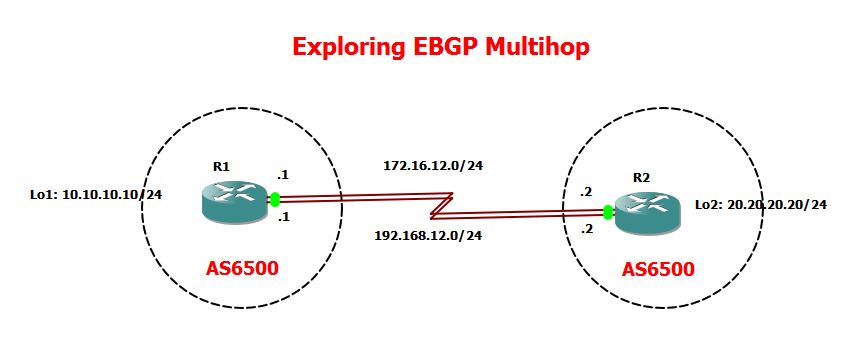